3D TRASAR
5500 - Installation & Operation Manual
521-OM0108.88
Copyright
2009 Nalco Company
2-47
Technical Help
(630) 305-CHEM
2.7.16 Alarm Output Connections
(User Wired in Controller Box or Junction Box)
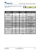
There are two different alarm outputs. The first is a
general alarm (fused @ 1.0 amp) that is initiated by any
of the alarms described in Section 4.11.
The second alarm output is a float switch alarm that is only used with 3D TRASAR models that are
fully enclosed. This alarm is initiated if water starts accumulating in the enclosure. This alarm
should be sent to a location where it can be responded to as quickly as possible to avoid damaging
the electronics.
Connection
Description
Controller Box
Board Reference
Controller Box Terminal
(Removable
Connector)
Junction Box Terminal
General System
Alarm
TB8-1
COM
ALARM - COM
TB8-2
NO
ALARM - NO
TB8-3
NC
ALARM - NC
Float Switch
Alarm
Terminations made
at float switch
N/A
N/A
2.7.17 Phone Line Connections
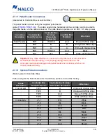
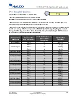
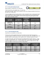
A phone line can be connected to the 3D TRASAR controller. Through this modem connection you
can upload/download configurations, download history, and view live data. The phone line is also
required to transmit email alarms to users.
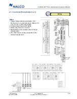
The phone line connection is located inside the controller box and can be connected through the
RJ11 analog phone jack or hardwired to terminals 1 and 2.
Wiring
1
2
RJ11 Analog
Phone Jack
Hard Wire Analog
Phone Connection*
Connection
Description
Controller Box
Board Reference
Controller Box Terminal
(or Phone Jack)
Junction Box
Terminal
Modem
(Phone Line)
TB-1
1
AP 1
TB-2
2
AP 2
Note
: Connect the analog “Tip” and “Ring” phone wires from the
telephone company to pins 1 and 2. The modem input is not polarity
sensitive, so it does not matter which order the wires are connected.

