521-OM0108.88
Copyright
2009 Nalco Company
4-19
Technical Help
(630) 305-CHEM
3D TRASAR
5500 - Installation & Operation Manual
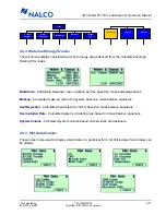
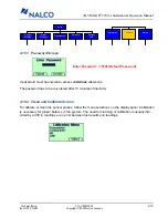
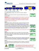
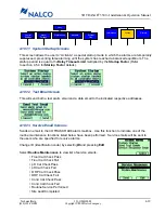
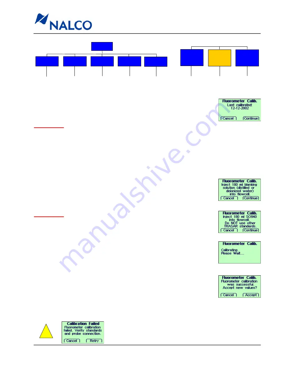
4.10.3 Fluorometer Calibration Screens
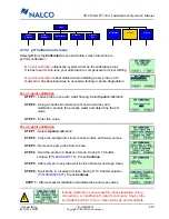
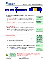
Select
Fluorometer
and follow screen directions to perform calibration:
STEP 1
Close fluorometer inlet valve and turn 3-way fluorometer discharge valve to
sample position.
IMPORTANT
: Bubbles trapped in fluorometer during injection can cause instru-
ment error. With the syringe
(P/N 500-P2147.88)
in a vertical position, tap the
syringe against a solid object to move the bubbles to the needle end of the
syringe. Then, force the bubbles out by pushing a small amount of solution
through the needle end of the syringe.
STEP 2
Clean the fluorometer by injecting acid with a syringe into the flow cell. Fill the
syringe with 60 ml of dilute acid. 10% Sulfuric Acid
(P/N 460-S0800.75)
is rec-
ommended. If iron fouling exists, use 1:1 HCl
(P/N 460-S0726.75)
for cleaning.
Screw the syringe onto the fitting, inject the dilute acid at a slow
, steady rate into
the flow cell, and allow it to stand for 2 minutes. Rinse well with water. Using the
flow cell brush
(P/N 500-P2817.88)
, gently push the brush down through the
opening and scrub the full length of the flowswitch and fluorometer tube.
IMPORTANT
: If using 1:1 HCl, do not leave the acid in the flow cell for more than
five minutes.
STEP 3
Following the screen prompts, use a second clean 60 ml syringe and slowly
flush the flow cell with 180 ml of blank solution. Then slowly inject another 180 ml
blank solution and allow it to remain in the flow cell by leaving the syringe at-
tached. Press
Continue
.
STEP 4
Following the screen prompts, use a third clean 60 ml syringe and slowly inject
the flow cell with 180 ml of calibration solution
(P/N 460-S0940.75)
and allow it
to remain in the flow cell by leaving the syringe attached. Press
Continue
.
STEP 5
Successful calibration will be indicated and must be “accepted”. Controller will
automatically re-boot after accepting calibration. Turn valves back to operating
positions.
Control
Settings
Alarm
Settings
Preferences
System
Info
Network
Information
Manual
Relay
Actions
Menu
Alarms
!
A failed calibration is most likely caused by insufficient flush-
ing, contaminated/incorrect standards, introduction of air
bubbles, excessive cell fouling, or a bad probe connection.

