NB19-E01
Products Manual
NRD-1300,1600
Nambuk Co., Ltd.
21
6. Product Operation
6-1. Power Input of Product
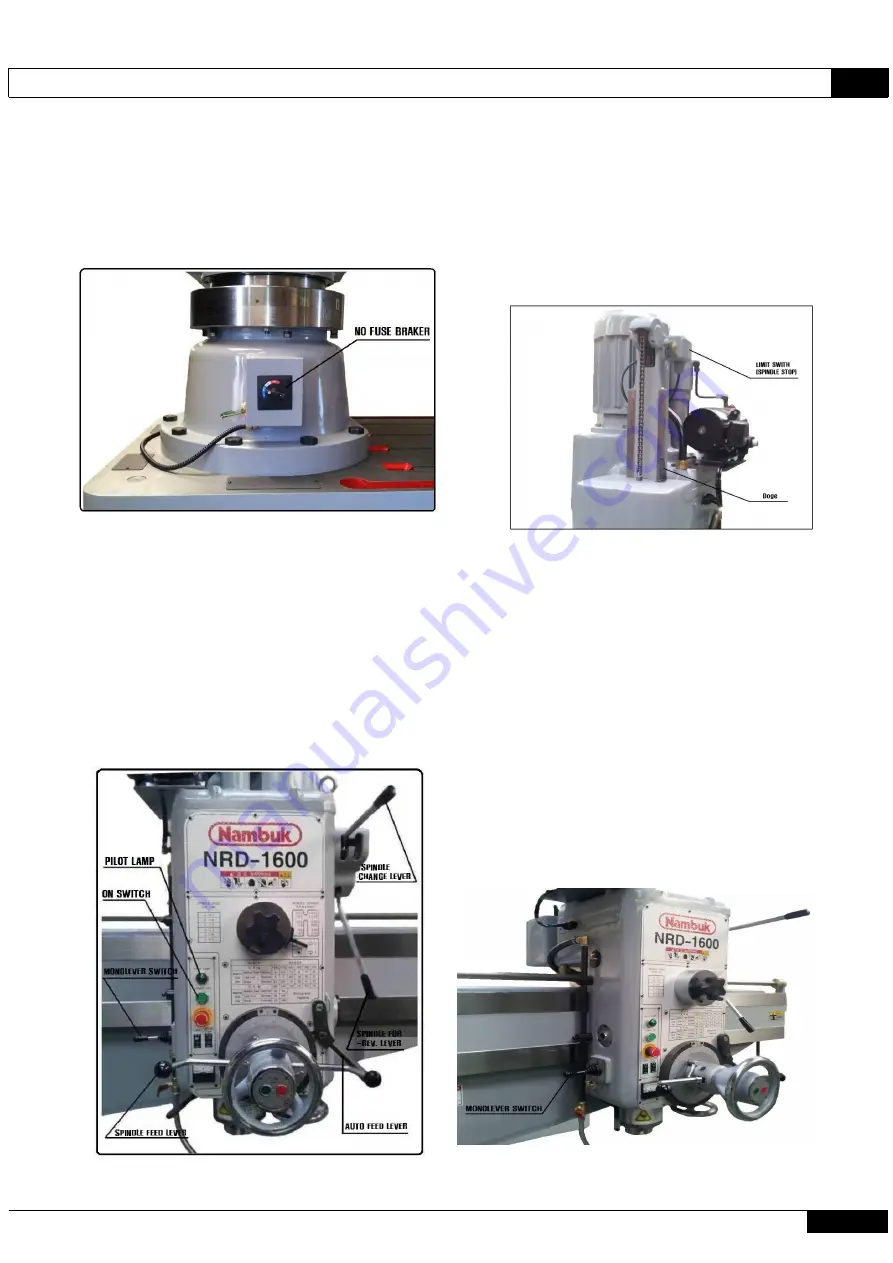
The power will be connected by lifting the breaker
switch at the bottom front of the column and
pressing the "ON" switch at the control panel on the
left-hand side of the box, and the Pilot Lamp will
be turned on.
6-3. Feed of Spindle
The spindle will be in auto-feed by placing the
auto-feed lever on the left-hand side when the
spindle rotates forward and by pulling the spindle
feed lever toward the worker.
If the spindle is fed to 300mm in this machine, a
limit switch is installed to stop the spindle motor.
6-2. Rotational Direction of Spindle
If a mono lever switch is pushed back after changing
the spindle revolution to the lowest revolution, the
spindle will rotate forward, and if the mono lever
switch is pulled, the spindle will rotate in
reverse.
If a spindle forward/reverse switching lever is
pulled down from the middle position, the spindle
will rotate forward (drill cutting direction). If
the spindle forward/reverse switching lever is
pulled up from the middle position, the revolution
of the spindle will increase and the spindle will
rotate in reverse.
6-4. Ascending and Descending of Arm
If a mono lever switch is pulled up ( ), the arm
⇧
will ascend after the top & bottom screws of the arm
rotate at an idle velocity for a few seconds to
release the arm clamp. If the mono lever switch is
placed at the middle position, the arm will stop
ascending and the top & bottom screws of the arm
will rotate at a fixed velocity toward the opposite
direction for a few seconds to clamp the arm. If the
mono lever switch is pulled down ( ), the top &
⇩
bottom screws of the arm will rotate at a fixed
velocity (release of arm clamp) and the arm will
descend.
If the mono lever switch is placed at the middle
position, descension will stop and screws will
rotate at a fixed velocity in the opposite direction
to clamp the arm.
Summary of Contents for NRD - 1300
Page 31: ...Products Manual NB19 E01 NRD 1300 1600 30 Nambuk Co Ltd 8 2 Electric Circuit Diagram 2...
Page 32: ...NB19 E01 Products Manual NRD 1300 1600 Nambuk Co Ltd 31 8 2 Electric Circuit Diagram 3...
Page 34: ...NB19 E01 Products Manual NRD 1300 1600 Nambuk Co Ltd 33 8 2 Electric Circuit Diagram 5...
Page 36: ...NB19 E01 Products Manual NRD 1300 1600 Nambuk Co Ltd 35 8 4 Electrical part layout...
Page 37: ...Products Manual NB19 E01 NRD 1300 1600 36 Nambuk Co Ltd 9 PARTS LIST...
Page 39: ...Products Manual NB19 E01 NRD 1300 1600 38 Nambuk Co Ltd 9 PARTS LIST...
Page 41: ...Products Manual NB19 E01 NRD 1300 1600 40 Nambuk Co Ltd 9 PARTS LIST...
Page 43: ...Products Manual NB19 E01 NRD 1300 1600 42 Nambuk Co Ltd 9 PARTS LIST...
Page 45: ...Products Manual NB19 E01 NRD 1300 1600 44 Nambuk Co Ltd 9 PARTS LIST...
Page 47: ...Products Manual NB19 E01 NRD 1300 1600 46 Nambuk Co Ltd 9 PARTS LIST...
Page 49: ...Products Manual NB19 E01 NRD 1300 1600 48 Nambuk Co Ltd 9 PARTS LIST...
Page 51: ...Products Manual NB19 E01 NRD 1300 1600 50 Nambuk Co Ltd 9 PARTS LIST...
Page 53: ...Products Manual NB19 E01 NRD 1300 1600 52 Nambuk Co Ltd 9 PARTS LIST...
Page 55: ...Products Manual NB19 E01 NRD 1300 1600 54 Nambuk Co Ltd 9 PARTS LIST...


