Products Manual
NB19-E01
NRD-1300,1600
24
Nambuk Co., Ltd.
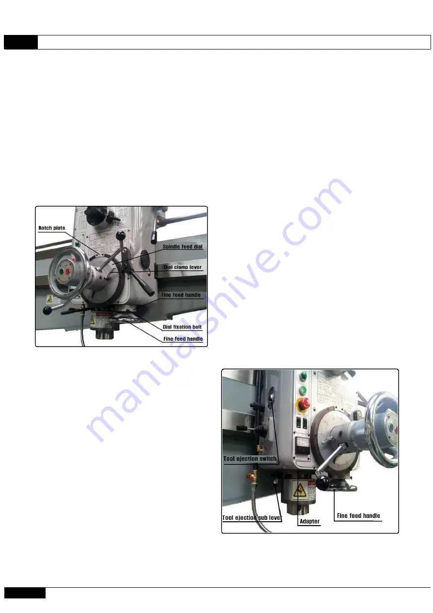
6-10. Micro Feed of Spindle
If the spindle feed lever is placed at the
micro feed position and the micro feed handle
is turned by hand, micro feed of the spindle is
enabled.
The scale dial of the micro feed is imprinted
by the 0.025cm unit gap.
If the handle is rotated once, 2.35mm will be
fed.
6
-12. Ejection of Tool
The tool ejector of this machine has been
manufactured for the hydraulic type.
Method
For manual ejection, if the tool is pulled up
to the spindle section by the spindle feed
handle, the handle lever is pulled, the tool is
held with the right hand, and the tool ejector
button installed at the left-hand side is
pressed with the left hand, the tool will be
ejected from the spindle. At this time, please
make sure to work by holding the tool with one
hand lest the tool falls on the machine or the
processed object.
During tool attachment or processing, please
attach the tool or use it while processing by
pushing the auxiliary lever for tool ejection
to prevent the spindle sleeve section from
touching the adaptor section lest the tool
falls. The lever for tool ejection will return
automatically.
6-11. Selection of
Auto Feed
Depth of
Spindle
The spindle feed dial is marked in black
(0~117), green (118~235), and red (236~300),
and the process is possible up to the selected
depth.
For the feed depth, after the depth of the hole
for the process is selected with the spindle
feed dial on the scale plate and two dial clamp
levers are tightened, feeding will be stopped
at position "0" of the dial scale.
After the depth of the auto feed is selected,
auto feed is possible if the auto feed lever
and spindle feed lever are placed at the auto
feed position as shown in Clauses 5-9.
If feeding is completed as much as the selected
depth, the auto feed lever will return to its
original position and auto feed will be
stopped.
Summary of Contents for NRD - 1300
Page 31: ...Products Manual NB19 E01 NRD 1300 1600 30 Nambuk Co Ltd 8 2 Electric Circuit Diagram 2...
Page 32: ...NB19 E01 Products Manual NRD 1300 1600 Nambuk Co Ltd 31 8 2 Electric Circuit Diagram 3...
Page 34: ...NB19 E01 Products Manual NRD 1300 1600 Nambuk Co Ltd 33 8 2 Electric Circuit Diagram 5...
Page 36: ...NB19 E01 Products Manual NRD 1300 1600 Nambuk Co Ltd 35 8 4 Electrical part layout...
Page 37: ...Products Manual NB19 E01 NRD 1300 1600 36 Nambuk Co Ltd 9 PARTS LIST...
Page 39: ...Products Manual NB19 E01 NRD 1300 1600 38 Nambuk Co Ltd 9 PARTS LIST...
Page 41: ...Products Manual NB19 E01 NRD 1300 1600 40 Nambuk Co Ltd 9 PARTS LIST...
Page 43: ...Products Manual NB19 E01 NRD 1300 1600 42 Nambuk Co Ltd 9 PARTS LIST...
Page 45: ...Products Manual NB19 E01 NRD 1300 1600 44 Nambuk Co Ltd 9 PARTS LIST...
Page 47: ...Products Manual NB19 E01 NRD 1300 1600 46 Nambuk Co Ltd 9 PARTS LIST...
Page 49: ...Products Manual NB19 E01 NRD 1300 1600 48 Nambuk Co Ltd 9 PARTS LIST...
Page 51: ...Products Manual NB19 E01 NRD 1300 1600 50 Nambuk Co Ltd 9 PARTS LIST...
Page 53: ...Products Manual NB19 E01 NRD 1300 1600 52 Nambuk Co Ltd 9 PARTS LIST...
Page 55: ...Products Manual NB19 E01 NRD 1300 1600 54 Nambuk Co Ltd 9 PARTS LIST...


