background image

NB19-E01

                                                                                                    Products  Manual

NRD-1300,1600

Nambuk  Co.,  Ltd. 

35

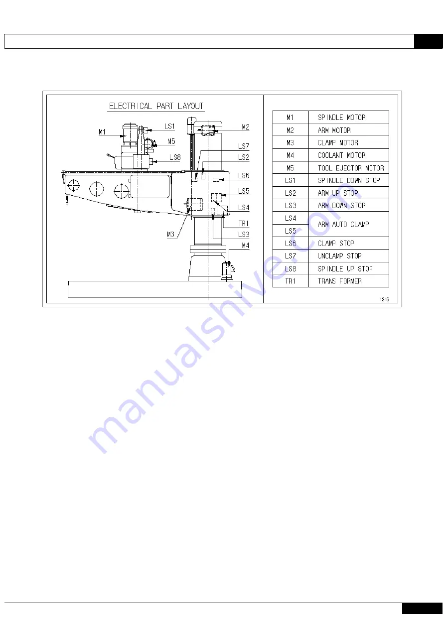
         8-4 Electrical part layout


Summary of Contents for NRD - 1300

Page 1: ...1600 1 Please make sure to read the product manual before use 2 The operator should have full knowledge of the manual before use 3 The said product has been manufactured according to the Korea Capaci...

Page 2: ...12 3 1 Product Specification 3 2 Terms of Each Machine Part 3 3 Accessories 4 Product Characteristics 14 4 1 Spindle Box 4 2 Spindle 4 3 Spindle Motor Gear 4 4 Feed Gear 4 5 Spindle Transmission Devi...

Page 3: ...lanation of Electric Circuit Diagram 8 4 Electrical part layout 9 PARTS LIST 36 10 Reference Materials 56 10 1 Plate Name of Manufacturing No 10 2 Protection Guard Manufacturing Diagram 11 Cutting Dat...

Page 4: ...ience operates the machine it will cause machine failure or a personal accident There are various types of processed objects the user processes Please carry out the processing conditions of the proces...

Page 5: ...of Warning Marks Warning marks attached to this product manual and equipments are classified to the following 4 stages An exceedingly dangerous condition if the user of this machine or the third pers...

Page 6: ...nd equipments use the following symbols and require careful attention Caution Danger Warning Electric shock Prohibited Do not approach Injury by rotation tool Do not disassemble Scattering Do not use...

Page 7: ...g of chips As there is a risk of injury from the scattering of chips and coolant on the eyes or face during the process please make sure to wear protective gear Gloves prohibited during work If you we...

Page 8: ...condition cutting condition attachment condition of tools and clamp condition of the processed objects before operation 3 Please input the power in order of the operation switches of the power control...

Page 9: ...to an abnormal condition of the machine Pleas do not operate a switch with a wet hand Please make sure to ground the machine and do not ground on improper places such as a gas pipe Label Attachment Po...

Page 10: ...let the hands get jammed between the pulley and belt Please do not wear gloves during operation They may be jammed in the rotational part If the machine stops during operation due to abnormal electric...

Page 11: ...resent Please check the position of the emergency stop button in order to immediately disable it in an emergency situation When repairing inspecting or exchanging tools please make sure to work after...

Page 12: ...fe and normal way During use there is a concern of bodily injury if the product hits a part of a person s body During work please check the protection guard and make sure to wear safety protection gea...

Page 13: ...2336 2560 Max height of machine H mm 2754 2954 Base size mm 2120 870 215 2480 1050 240 Vertical traverse distance of arm mm 655 840 Size of base working surface mm 1420 850 1750 1030 Net weight kg 3...

Page 14: ...lumn sleeve clamp shaft 5 Column sleeve 16 Spindle forward reverse lever 27 Clamp box cover 6 Arm 17 Spindle feed transmission lever 28 Electric box 7 Arm elevation screw 18 Auto manual feed transmiss...

Page 15: ...t Characteristics 4 1 Spindle Box In the spindle box a gear box is installed at the top a feed gear box in the middle a spindle feed device at bottom and feed devices on the left and right Each contro...

Page 16: ...art protects the machine from overload by using an overload relay and reverse protection relay 4 5 Spindle Transmission Device 12 speed transmission and forward reverse rotation of spindle with two le...

Page 17: ...ng up the machine please recheck the centers of the rope and machine Transportation Method of Machine During transportation of the machine please adjust the center equivalent to the unloading method f...

Page 18: ...is secured on the solid ground for convenient work and maintenance For the foundation please increase or decrease the thickness of the concrete according to the ground in order to prevent sinking or...

Page 19: ...NRD 1300 1600 18 Nambuk Co Ltd Usage range The rotation of the arm should be within the range of 90 45 to 45 shown below There is a risk that the machine will be overturned Machining should be done wi...

Page 20: ...tion of the arm and clamp it to the column sleeve 6 Please place a 1 100mm level on the top surface of the base to adjust the left right balance with a leveling bolt Please tighten the nut of the base...

Page 21: ...spindle box clamp 2 sites proper amt once a week B1 Column sleeve slideway face proper amt once a week Slideway oil B2 Arm slideway face proper amt once a week Tona S2 M68 B3 Oil tank for arm elevati...

Page 22: ...se If a spindle forward reverse switching lever is pulled down from the middle position the spindle will rotate forward drill cutting direction If the spindle forward reverse switching lever is pulled...

Page 23: ...the spindle box is possible 6 6 Selection of Spindle Revolution The selection of spindle revolution is possible for 38 1975 RPM 12 speed transmission with the spindle transmission lever and forward re...

Page 24: ...fter the feed speed of the spindle is selected when the spindle feed lever is pulled and the auto feed lever is pushed to the left hand side auto feed is enabled In order to stop auto feed manually pl...

Page 25: ...lls on the machine or the processed object During tool attachment or processing please attach the tool or use it while processing by pushing the auxiliary lever for tool ejection to prevent the spindl...

Page 26: ...the clamp strength is weak please adjust the clamping amount by gear Please remove the bracket and cover if the spindle box clamp is loose Please separate the clamp shaft from the gear assemble the ge...

Page 27: ...fter adjusting the friction force please fixate the fastening plate and the pin on the pin hole closest to the adjusted position Please adjust the multi disk clutch to slip at the current of the ammet...

Page 28: ...eaker and a ground wire to the ground mount inside the external control handle box at the bottom of the column Please rewire by switching two of the three phases of the R S T if the lamp is not lit af...

Page 29: ...K25 81N29 1b Power cut off MS1 Magnetic contactor MC 22b Spindle forward rotation PB2 Push button switch KPB 25M 10 Power connection MS2 Magnetic contactor MC 22b Spindle reverse rotation PB3 Micro P...

Page 30: ...ctric Circuit Diagram 1 N R D 1 3 0 0 1 6 0 0 M O D E L 0 7 0 0 6 5 0 6 0 0 5 5 0 4 5 0 5 0 0 4 0 0 3 5 0 3 0 0 2 5 0 1 5 0 2 0 0 1 0 0 0 5 T I T L E N a m b u k C o L t d 4 1 1 3 E 0 0 0 1 1 4 S T A...

Page 31: ...Products Manual NB19 E01 NRD 1300 1600 30 Nambuk Co Ltd 8 2 Electric Circuit Diagram 2...

Page 32: ...NB19 E01 Products Manual NRD 1300 1600 Nambuk Co Ltd 31 8 2 Electric Circuit Diagram 3...

Page 33: ...M O T O R A R M C O V E R 1 3 E 0 0 0 2 4 4 2 0 1 3 0 4 0 4 N R D 1 3 0 0 M O D E L T I T L E K I V 0 7 5 S Q K I V 0 7 5 S Q K I V 2 5 S Q K I V 1 5 S Q K I V 0 4 S Q K I V 1 5 S Q Y G Y G Y G Y G Y...

Page 34: ...NB19 E01 Products Manual NRD 1300 1600 Nambuk Co Ltd 33 8 2 Electric Circuit Diagram 5...

Page 35: ...gency Stop Switch The power is cut off if pressed in an emergency Red PB5 Push button switch Tool ejection switch Black MLS Mono lever switch If operating toward the corresponding direction the spindl...

Page 36: ...NB19 E01 Products Manual NRD 1300 1600 Nambuk Co Ltd 35 8 4 Electrical part layout...

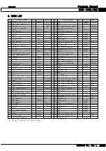
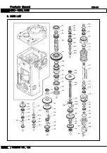
Page 37: ...Products Manual NB19 E01 NRD 1300 1600 36 Nambuk Co Ltd 9 PARTS LIST...

Page 38: ...ew 8 M4 6 20 Name plate 1 13N008 64 Lamp 1 20W 21 Cover 1 13C034 65 Cross recessed head screw 2 M4 6 22 No fuse breaker 1 ABS33 3P30A 66 Rack 3 13A081 23 Cross recessed head screw 4 M4 40 67 Hex socke...

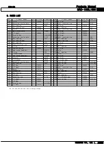
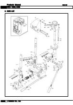
Page 39: ...Products Manual NB19 E01 NRD 1300 1600 38 Nambuk Co Ltd 9 PARTS LIST...

Page 40: ...3230R 110 Steel ball 6 7 160 Collar 1 13A040 111 Spring 6 13A007 161 Shaft 1 13A038 112 Safety clutch 1 13A006 162 Parallel key 1 10 8 95 113 Pin 6 13A008 163 Parallel key 1 10 8 48 114 164 Cam 2 13A0...

Page 41: ...Products Manual NB19 E01 NRD 1300 1600 40 Nambuk Co Ltd 9 PARTS LIST...

Page 42: ...205 Hex socket head bolt 6 M6 12 243 2 Rivet 4 2 6 206 Ball bearing 1 6205 244 Setscrew with hex socket 8 M6 10 207 Collar 1 13A061 245 Roller 3 13C030 208 Cover 1 13A062 245 1 Roller 1 13C030 1 209...

Page 43: ...Products Manual NB19 E01 NRD 1300 1600 42 Nambuk Co Ltd 9 PARTS LIST...

Page 44: ...S027 282 O Ring 1 G60 313 Ball bearing 1 6211LLU 283 Bearing housing 1 13S005 314 Oil seal 1 SC507009 284 Hex socket head bolt 4 M6 12 315 Collar 1 13S026 285 O Ring 1 P36 316 Ball bearing 2 6205 286...

Page 45: ...Products Manual NB19 E01 NRD 1300 1600 44 Nambuk Co Ltd 9 PARTS LIST...

Page 46: ...Change rod 1 13S053 342 Spring 3 13S040 369 Pin 1 13S057 343 Spring washer 3 M10 370 Split pin 1 2 16 344 Set screw with hex socket 3 M10 30 371 Change lever 1 13S056 345 Hexagon nut 3 M10 372 Shifte...

Page 47: ...Products Manual NB19 E01 NRD 1300 1600 46 Nambuk Co Ltd 9 PARTS LIST...

Page 48: ...1 Hex socket head bolt 4 M6 16 410 Thrust ball bearing 1 51115 392 Stopper 1 13S067 411 Collar 1 13S075 393 Pin 1 13S066 412 Roller bearing 1 NN3015KP5 394 Lever 1 13S068 413 Collar 1 13S074 395 Nut 1...

Page 49: ...Products Manual NB19 E01 NRD 1300 1600 48 Nambuk Co Ltd 9 PARTS LIST...

Page 50: ...SC18307 495 Parallel key 1 5 5 12 446 Cover 1 13T010 496 Collar 1 13F014 447 Hex socket head bolt 4 M5 10 497 Ball bearing 2 6003 448 Dial 1 13T011 1 498 30T Gear 1 13F013 449 Set bolt 1 13T011 2 499...

Page 51: ...Products Manual NB19 E01 NRD 1300 1600 50 Nambuk Co Ltd 9 PARTS LIST...

Page 52: ...Needle roller bearing 3 NK30 20R 573 Slide key 2 13T039 540 Shaft gear 1 13T021 574 Key holder 1 13T040 541 Parallel key 2 5 4 45 575 Needle roller bearing 1 NK20 20R 542 Oil seal 1 SC507212 576 Adapt...

Page 53: ...Products Manual NB19 E01 NRD 1300 1600 52 Nambuk Co Ltd 9 PARTS LIST...

Page 54: ...essed head screw 15 M3 6 672 Motor 1 13E001 3 7KW 4P 616 Ammeter 1 WY R05AA 673 Parallel key 1 7 7 25 617 Cross recessed head screw 3 M3 8 674 24T Motor gear 1 13S003 618 Name plate 1 13N003 675 Lock...

Page 55: ...Products Manual NB19 E01 NRD 1300 1600 54 Nambuk Co Ltd 9 PARTS LIST...

Page 56: ...A PT1 8 764 Cover 1 13S031 R 2 717 Male connector 1 PT1 8 4 765 Idle cover 1 13P025 R 1 718 Copper pipe 1 4 766 Hex socket head bolt 4 M8 20 719 Male connector elbow 1 PT1 8 4 90 767 Cylinder body 1 1...

Page 57: ...o n g g i d o K o r e a 2 1 0 4 2 4 B a e g o k d a e r o M o h y e o n m y e o n C h e o i n g u T e l N o 8 2 3 1 3 3 3 1 4 2 1 S u r g e p r o t e c t i o n p r o v i d e d a t m a c h i n e s u p...

Page 58: ...50 80 Reamer SKH 3 5 4 6 4 6 6 12 8 10 Tap SKS 3 6 4 8 4 8 8 12 6 12 11 2 Standard Feed Amount Unit mm rev Tool Material Hard Steel Mild Steel Cast Iron Copper Alloy Al Alloy Drill mm 3 5 0 13 0 13 0...

Page 59: ...Gu Busan Metropolitan City Tel 051 941 8746 Fax 051 941 5820 Daegu Marketing Office Ilheung Biulding 303 188 Gosung Ro Buk Gu Daegu Metropolitan City Tel 053 353 6221 Fax 053 353 6983 Homepage www nbm...

Reviews: