Page 40
5-5-3
Adjusting the Sensors
Sensor adjustment is performed while power to the machine is ON. To
prevent electric shock, accident or injury, do not touch any parts other
than those specified in the following sections.
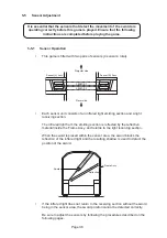
The Frame assembly is an important part in the correct function of the sensors.
Please check that each part of the Frame assembly is fitted correctly and that the
reflective material on the inside of the Frame assembly is clean and smooth (no
cracks or bubbles).
Ensure that the glass sensor covers are clean, both inside and outside.
When “(I/O PCB ERROR”) is displayed on the screen, check the connection of the
USB cable first.
After “NAOMI” LOGO is displayed, the self-test is started.
If adjustment of the sensors is incorrect, the error message is displayed on the
screen. Perform the following procedures to adjust the sensors for correct operation.
•
When conducting the sensor adjustment, do not place any object, arm or sword
inside the sensor area.
•
Infrared light deteriorates through glass. Please adjust the sensors without
removing the glass covers.
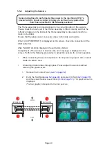
1.
Remove the Control Panel.
(see 7-6 page 72)
2.
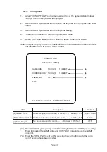
Enter the Test Mode (
see 6-2 page 46)
and select I/O Test
(6-2-3 page 50)
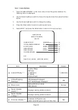
and then select Sensor Level Check
(6-2-3-2 page 51)
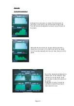
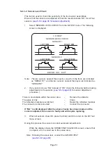
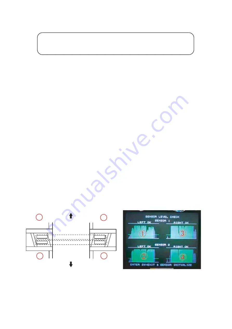
. The graph screen is
displayed.
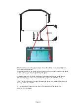
The four graphs correspond to the four sensors.
1
3
2
4
SENSOR 1
SENSOR 2
LEFT SENSOR ASSY
RIGHT SENSOR ASY
MONITOR
PLAYER


