Page 73
4.
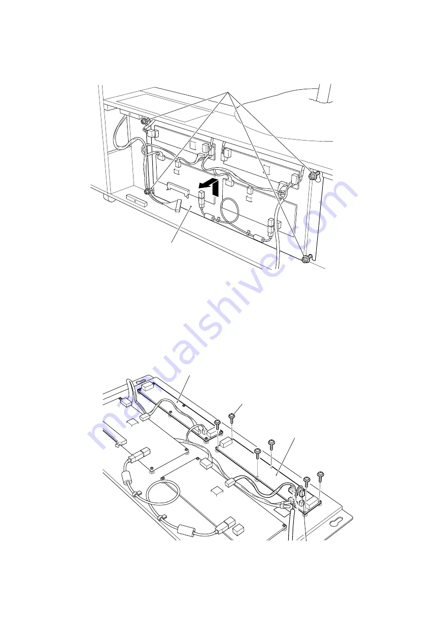
Remove the 2off upper pozi head screws (M6x25), with flat and spring washers,
and loosen the 2off lower screws, and remove the PCB Base.
5.
Disconnect the connectors.
6.
Remove 6off pozi head screws (M5x25), with flat and spring washers, and
remove the Sensor PCB.
7.
Re-assemble in reverse order.
Pozi head screw (M6 x 25)
(with flat and spring washers)
PCB base
Pozi head screw (M5 x 25)
(with flat and spring washers)
Sensor PC board
(for SENSOR 2 (on player side))
Connector
Sensor PC board
(for SENSOR 1 (on projector side))

