© by N&W GLOBAL VENDING S.p.A.
47
05-2015 3625 01
REMovINg TRays
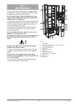
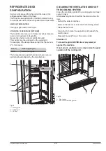
To replace the tray, act as follows:
-
pull the tray as far as the limit stop;
-
detach the electrical connector from the tray;
-
lift the tray to unlock the retaining chute.
-
act in the reverse order to assemble another tray.
1
2
3
4
Fig. 29
ChaNgINg ThE NUMbER of TRays
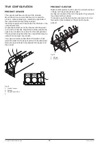
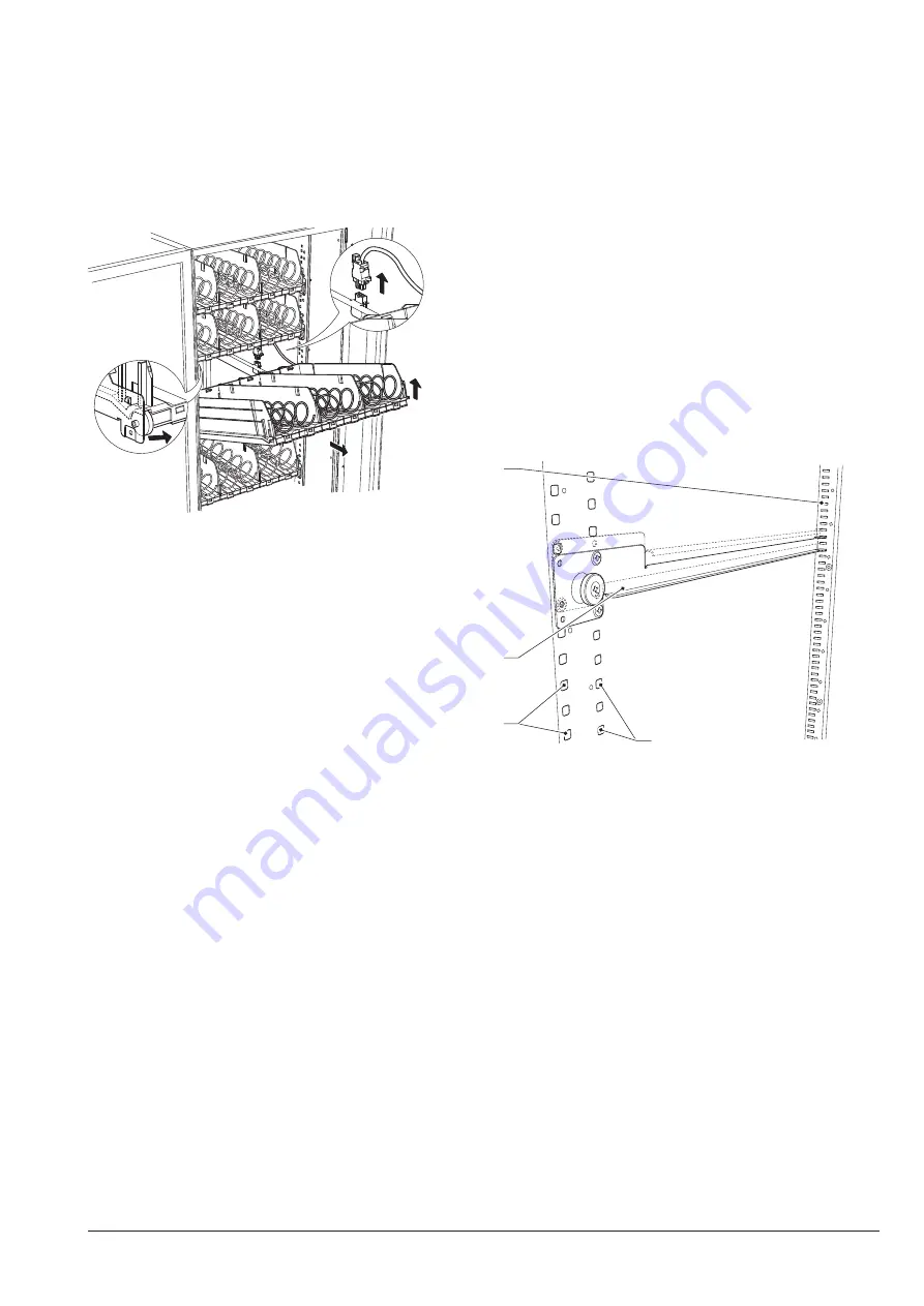
To change the number of trays, act as follows:
-
Detach the machine plug from the power mains.
-
Remove all trays from the V.M.
-
Move the tray guides as required; make sure that the
guide is first inserted into the coupling slots and then
secured by means of 2 screws by using the most ap
-
propriate fastening holes.
-
Remove the pair of guides, if not used.
-
Reassemble the trays by making sure that the connec
-
tors are inserted properly.
-
Secure the wiring that has remained free to prevent it
from hampering the movement of the other trays and
the relative wiring.
-
Reprogramme the machine by using the "machine con
-
figuration" function from the technician menu "Config
-
ure machine".
1
2
2
3
Fig. 30
1- Tray guide
2- Guide fastening holes
3- Coupling slots

