38
S06
INSTRUMENTATION
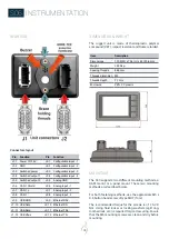
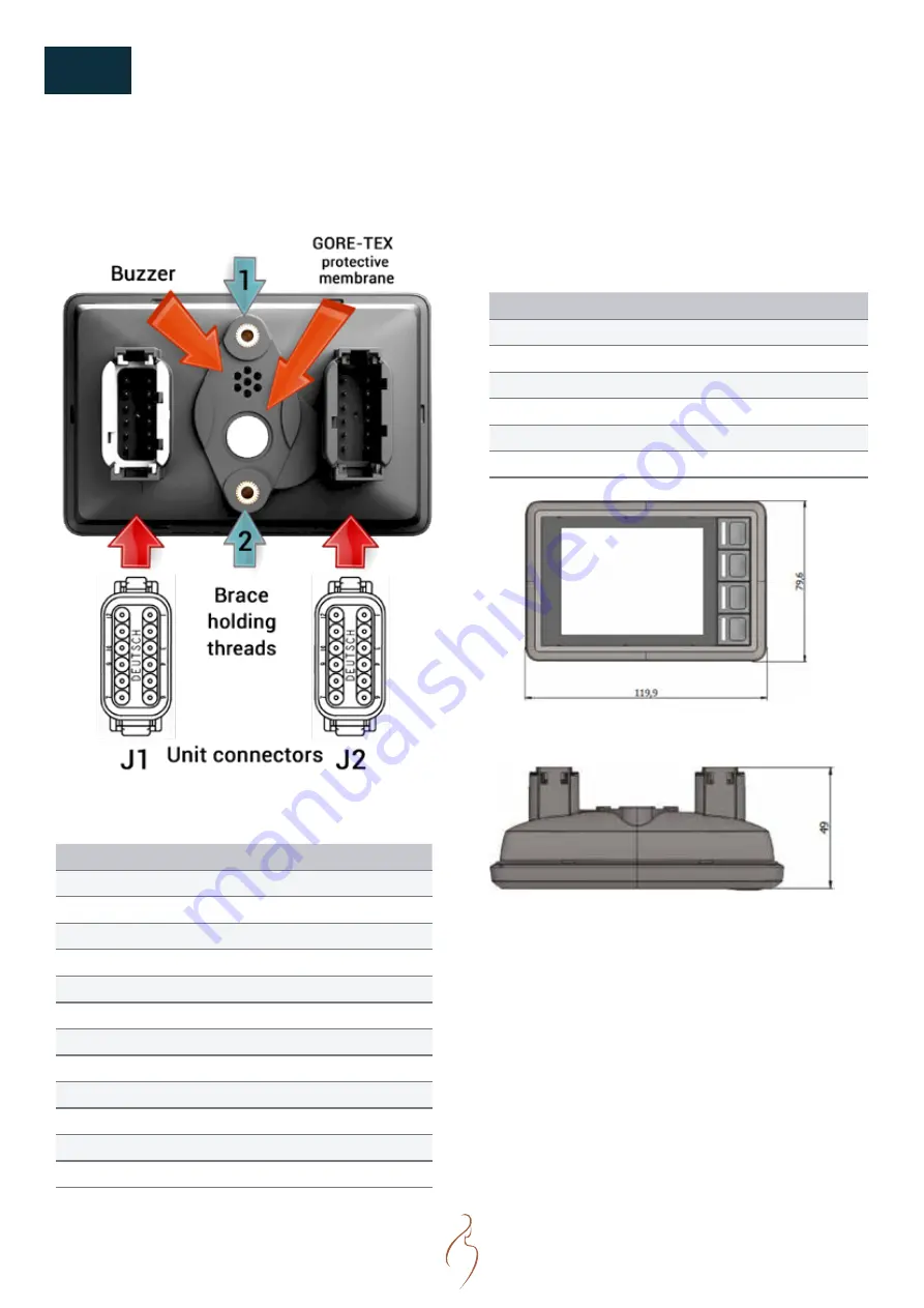
REAR SIDE
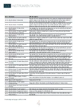
Connectors layout
Pin Function
Pin
Function
J1-1 Power 12/24V
J2-1
Configurable input -1
J1-2 GND
J2-2
Configurable input -2
J1-3 Switched power
J2-3
Configurable input -3
J1-4 Switched output 1
J2-4
Configurable input -4
J1-5 Switched output 2
J2-5 Analog GND
J1-6 CAN 1 Shield
J2-6 Analog input - 1
J1-7 CAN 1 +
J2-7 Analog input - 2
J1-8 CAN 1 -
J2-8 Analog input - 3
J1-9 USB GND
J2-9 Ethernet RD+
J1-10 USB Data -
J2-10 Ethernet RD-
J1-11 USB Data-
J2-11 Ethernet TD+
J1-12 USB Vbus
J2-12 Ethernet TD-
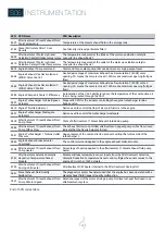
DIMENSIONS & WEIGHT
The rugged unit is made of thermoplastic polymer
compound (PBT), impact resistant and flame retarded.
Item
Description
Dimensions
119,9 (W) x 79,6 (H) x 49 (D), in mm
Weight
0,250 kg
Spacing threads
48,5 mm
Threads dimension M5
Threads depth
7,7 mm
Enclosure
PBT+ PC plastic
MOUNTING
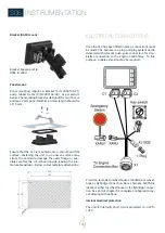
The SI.3 supports two different mounting methods, a
RAM mount or a panel mount. These two mounting
methods are described below.
For both fastening methods, use the appropriate M5 x
0.8 button head screw of type MRT (Torx).
The recommended torque for the screws is of 1.5-2.0
Nm. Using fluid locker or locking washers (split ring,
toothed lock, etc.) is required for good securing. Ensure
that the M5 mounting screws are clean and dry before
mounting.
Summary of Contents for N16.1000 CR3
Page 2: ......
Page 4: ......
Page 34: ...34 S05 COMPONENTS ENGINE VIEWS N16 CR3...
Page 35: ...35 NOTES...
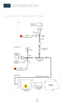
Page 48: ...48 S06 INSTRUMENTATION SYSTEM LAYOUT INCLUDING OPTIONS...
Page 118: ......

