50
S07
STARTING & RUNNING
BEFORE STARTING
FUEL SYSTEM
The fuel is drawn from the tank by the fuel feed pump
and is injected into the combustion chamber by the
injection pump. A fuel filter is placed between the feed
pump and the injection pump.
The injection pump delivers a larger amount of fuel than
required for combustion. The fuel that is not burned is
re-injected into the tank through an over-flow pipe.
CAUTION !
The injection pump is an extremely precise unit. Water
entry in the fuel system will cause major failure to the
injection pump and to the whole fuel system.
A fuel prefilter with a water separator should be installed
between the fuel tank and the fuel filter on the engine.
The prefilter should be installed as close as possible to
the engine fuel filter. It must never be installed on the
engine as vibrations affect the water/fuel separation
process.
If the fuel tank is located below the engine injection
pump, an additional electric fuel feed pump should be
installed between the prefilter and the feed pump of the
engine.
RAW WATER SYSTEM
The raw water system allows to cool the engine coolant
and the exhaust gas.
Raw water is drawn into the heat exchanger by the
engine raw water pump. The raw water is drained via the
exhaust elbow, where it is mixed with exhaust gases.
The siphon breaker prevents raw water entry into the
cylinders via the raw water/exhaust system.
NOTE !
The use of a siphon breaker is mandatory if the exhaust
elbow is under the waterline at full load or at less than
200 mm above it. A siphon breaker is mandatory in all
Sail Boat and when there’s a risk of water entry in the
engine.
A raw water filter must be fitted between the raw water
intake and the raw water pump of the engine.
NEUTRAL SAFEGUARD
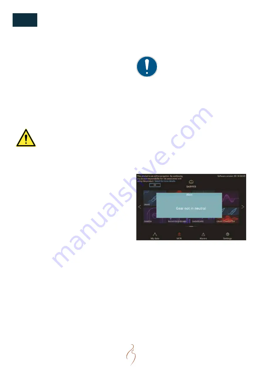
Once wired, the neutral safety switch from the engine
control box will display a warning message on the SI-7,
SI-9 or other similar control screen if transmission is
engaged forward or backward before engine crank:
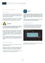
When this pop up appears, the engine will not start, un-
less transmission is put to neutral.
Summary of Contents for N16.1000 CR3
Page 2: ......
Page 4: ......
Page 34: ...34 S05 COMPONENTS ENGINE VIEWS N16 CR3...
Page 35: ...35 NOTES...
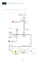
Page 48: ...48 S06 INSTRUMENTATION SYSTEM LAYOUT INCLUDING OPTIONS...
Page 118: ......

