background image

5. Removing the front panel

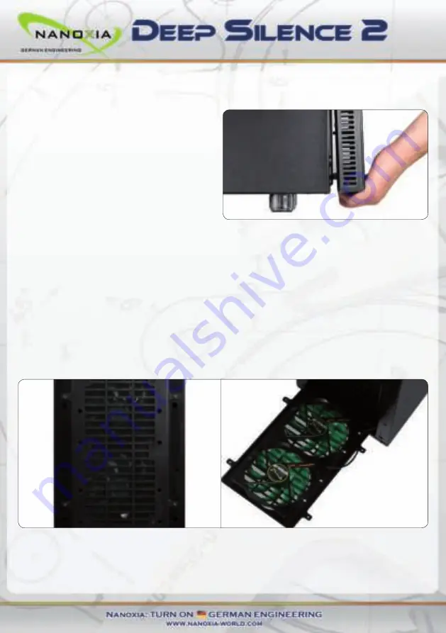
To remove the front panel, simply hold the 

cutout at the bottom of the front panel and 

pull it towards you with a firm tug. 


If you remove the front, please note the 

I / O panel cables at the top of the front. 

Please be cautious here.

6. Fan assembly and cleaning of the dust filters


The air intake openings in the front and at the bottom of the Deep Silence 2 are equipped with 

easy to clean dust filters. We recommend that you clean them on a regular basis. 


To clean the dust filter is usually sufficient to vacuum these carefully with a vacuum cleaner 

(low level). 


To switch the fans in the front or to clean the dust filters, please remove the front panel first.

Next, remove the four screws with which the dust filter is connected to the front and take it 

out.  


Please be advised that the fans are screwed to the dust filter.


The front dust filter allows the installation of either 2 x 120 mm or 1 x 140 mm fans. Two 

120mm Deep Silence fans ( approx. 1,300 rpm) are preinstalled. 

11

Summary of Contents for DEEP SILENCE 2

Page 1: ......

Page 2: ...________18 ___________________________________18 ______________________________________19 _________________________________________20 I Introduction Specifications Accessories Features II Installation...

Page 3: ...ly the spacious interior can be used to install for example a water cooling system 240 mm radiator between the motherboard and the hard drive cage Specifications Dimensions 468 x 207 x 588 mm Height x...

Page 4: ...need them The removable Nanoxia VentCovers mask the 120 140 mm fan holes in the case top and the side panel They allow it to choose between the least possible noise and improved case ventila tion The...

Page 5: ...grated ventilation system consisting of three standard Deep Silence fans and a built in 2 channel fan controller for up to six fans A total of up to nine fans can be mounted To assist the ventilation...

Page 6: ...ter cooling system on the mounting bracket you should check before the installation whether the factory hoses between cooler and radiator are of sufficient length Rubber hose guides The Deep Silence 2...

Page 7: ...wing procedure 1 Please consult the following charts to find your motherboard form factor E ATX Mainboard ATX Mainboard Micro ATX Mainboard Mini ITX Mainboard 2 Attach the spacers according to your mo...

Page 8: ...on cable through the opening provided in the top left of the mainboard tray 6 Fix the motherboard to the motherboard tray 7 After the installation of the power supply you can connect the EPS extension...

Page 9: ...by pushing the slider back to its original position 2 Remove the 5 25 inch cover by pulling the lateral tilting lever cautiously towards you and take out the cover Then slide the drive into the desir...

Page 10: ...ame Then attach the card reader in the frame as shown below Then place the frame with the card reader back into the slot and lock the quick release Finally attach the included 3 5 inch adapter to the...

Page 11: ...the hard drive using the screws provided For the fitting of 3 5 inch hard drives please use the holes in Figure 4A marked red For the fitting of 2 5 inch hard drives please use the holes in Figure 4B...

Page 12: ...th easy to clean dust filters We recommend that you clean them on a regular basis To clean the dust filter is usually sufficient to vacuum these carefully with a vacuum cleaner low level To switch the...

Page 13: ...alled case fans and will work in perfect harmony with the built in fan control of your case Additional fans in the mounting bracket behind the HDD cage If you want to mount additional fans inside the...

Page 14: ...e Additional fan in the side panel If you want to accommodate a fan in the side panel please remove the Nanoxia Vent Cover first by unscrewing the screws on the outside of the case Please place the fa...

Page 15: ...ector that is connected directly to the power supply The controller has two channels A and B with each channel able to control up to three 3 pin fans therefore a total of six fans can be controlled Th...

Page 16: ...e right slider controls the fans of the second channel B1 B2 and B3 9 The I O Panel The I O panel includes connectors for external USB devices 2 x USB 3 0 1 x USB 2 0 and the microphone and headphone...

Page 17: ...rmance In order to fix a radiator on the Mounting Bracket you need to remove the mounting bracket as described in Chapter 6 Fan assembly and cleaning the dust filters Next set the radiator you to inst...

Page 18: ...11A If the pin allocation of the internal USB port is the one shown in diagram 11A it is then possible to connect the cable If however the pin allocation of the internal USB port and the one shown in...

Page 19: ...e to your hardware If your motherboard does not have internal USB 3 0 port you can acquire an internal 19 pin to external 2x USB 3 0 Type A adapter cable 11 3 HD Audio Diagram 11F shows the pin assign...

Page 20: ...l shown in diagram 11H If the pin allocation of the AC 97 plug and the one shown in diagram 11H are the same please connect the cable If however the pin allocation of the AC 97 plug and the one shown...

Page 21: ...suggestions and comments about our case very much Our staff will respond to all inquiries quickly and professionally Customers from Germany and the European countries can use the following e mail add...

Reviews: