background image

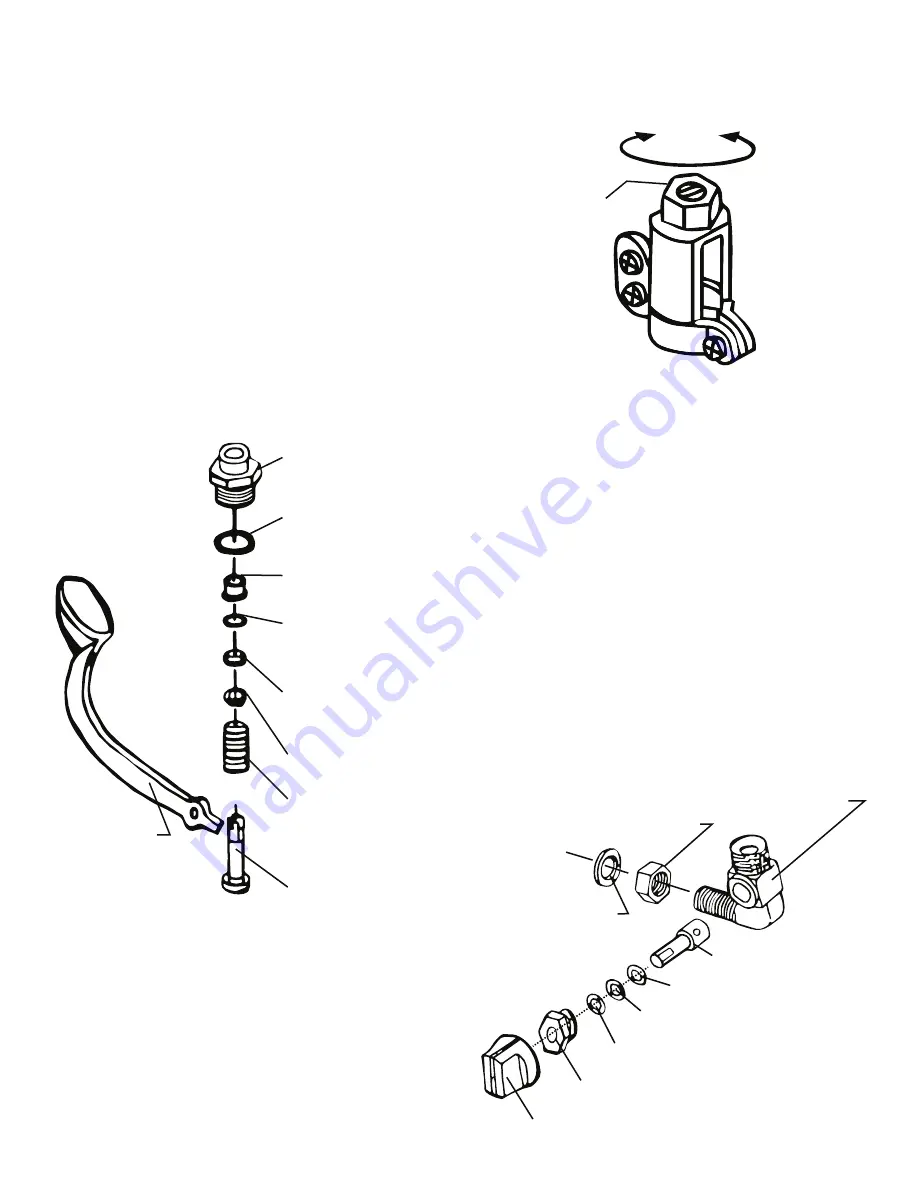
- Adjustment of Steam-Flow

This type of iron is so designed that the 

steam-flow from its base-plate can be 

adjusted. As shown in the following picture, 

first unfasten the plastic nut on top of the 

steam valve. Then, the steam-flow can be 

decreased by turning the control-screw 

clockwise with a s screwdriver, and vice versa

- Remove valve joint with spanner. 

- Further, remove wire, teflon bushing, O-ring, 

spindle washer and spring on this turn (see 

below drawing). 

- After finishing checking and replacement, 

assemble on the reverse turn.

- When assembling finished, install it on the 

iron as follows:

    - Insert the wire into the spindle again.

    - Install the metal fittng and the lever at last. 

Note:

When assembling, be sure to wind the seal 

tape on the valve joint 

Valve Joint

Copper Packing

Teflon Bushing

O - Ring (P6)

Cap Seal

Spindle Washer

Valve  Spring

Valve Spindle

Push Lever

(ie. the steam-flow can be increased turning 

the screw counter-clockwise).

Back-up Ring (Wht.)

Plastic Nut

Decrease

Increase

Be sure to refasten the plastic nut after the 

adjustment is completed. Please note that the 

above adjustment is solely intended for 

precision control of the steam-flow from the 

iron base-plate, this is completely separate 

from the steam pressure adjustment on the 

boiler. 

- Drain

if water drops or much drain come out with 

steam, check and treat as follows.

   - Abnormal pressure of the steam boiler.

      Consult your agent or our office.

   - Pipe line abnormality occured.

      Consult our office.

   - Inconvenience of draining function occured.

      Consult our office or refer to drawing below 

      and check the drain valve.

Drain Valve Body

Copper Packing

Spindle

Jam Nut

O-Ring(Viton) (Blk.)

O-Ring(Silicone)(Pnk.)

Spindle Sopper Screw

Drain Valve Knob

Summary of Contents for HSP Series

Page 1: ...NAOMOTO ALL STEAM IRON HSP series INSTRUCTION MANUAL HSP 440...

Page 2: ...ive in any way please contact the nearest Naomoto office or agent 2 If the iron is resold or rented to a third party please ensure that this manual accompanies the iron If the manual is unavailable as...

Page 3: ...as the Iron 1 1 pc Silicone Iron Rest 2 1 pc Mesh Filter 3 2 pc Packing 4 1 pc Inner Tube 5 1 pc O Ring P 4 6 1 pc O Ring Stopper 7 1 pc Joint Spring 8 1 pc Instruction Manual This booklet 3 NAMES OF...

Page 4: ...person CAUTION Do not apply the iron to any materials other than textile fabrics Some materals may easily melt scorch and or deform with heat WARNING Do not place inflammables chemicals or oils and f...

Page 5: ...tting the Special Extra Hose to the iron clean the inside of the hose by washing out any dust and dirst To do this first fix the Special Extra Hose to the boiler then open the boiler s steam valve and...

Page 6: ...the hose to the joint of the iron and fix it Installation of the Drain Hose Connect the mouth piece G1 4 of the drain hose to the drain hose joint of the iron and fix it Connection of the steam supply...

Page 7: ...MPa 6 2 Start of Operation Push the push lever to start steam At first water drops may come out with steam good steam comes out in a minute with the condition of appropriate draining CAUTION Sole pla...

Page 8: ...e check the symptoms and take necessary countermeasures outlined below where applicable If you need to replace any parts ask the nearest NAOMOTO office or its agent for the replacement parts WARNING B...

Page 9: ...ve Joint Copper Packing Teflon Bushing O Ring P6 Cap Seal Spindle Washer Valve Spring Valve Spindle Push Lever ie the steam flow can be increased turning the screw counter clockwise Back up Ring Wht P...

Reviews: