background image

791-9001 3  08/22/18

SETUP

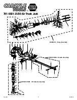
PLEASE REFER TO THE EXPLODED VIEW DRAWING IN THIS MANUAL IN ORDER TO IDENTIFY PARTS.

1.   Install the handle assembly (#79) in the housing (#74) 


so the holes in the lower portion of the handle line up 


with the holes in the housing. Push the handle yoke  


pivot shaft (#81) through all the holes and secure the 


shaft on both ends with the retaining rings provided.  

2. 

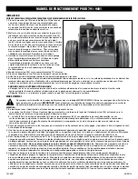
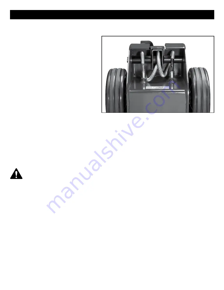
Turn the entire jack on its side in order to hook up the 


clear and black air hoses that are coming out of the 


bottom of the handle (#79). As you are facing the back 


of the jack, pull the clear and black hoses back towards 


you and route them over the top of the pivot  shaft (#81) 


so that they are in line to engage the connectors in 


the back of the tank (#105). Firmly push the black hose 


into the connector labeled "black tube" and the clear 


hose into the connector labeled "clear tube".  


Pull on both hoses after they are installed into the 


connectors to make sure they  are firmly seated. Turn 


the jack upright.   

3.    Install an air nipple that is suitable for your shop in the 
 

switch assembly (#77). Use pipe dope tape to seal the 


nipple in the switch assembly and be careful not to let 


any excess tape enter the air system. Do not 


over-tighten the nipple as this could strip the threads 


in the switch.  

4.   Install the lever (#106) in the switch assembly (#77) and tighten. 
5.    Install the adapters (#75) in the holder at the base of the housing.  
6.    Hook the shop air line quick disconnect onto the nipple.  
7.    Due to the back pressure release system design of this jack, the jack’s hydraulic system very rarely becomes air bound. Indication of an 
 

air bound system is a ram that does not rise smoothly. In some extreme case of an air bound system, air can be purged by following 


this procedure:              


PURGING AIR FROM THE HYDRAULIC SYSTEM 


a.  Pump the jack to maximum height by turning the air lever all the way to the right. After maximum height is reached, turn the air  


lever to the left to lower the jack all the way down.       


b.   Repeat step “a” several times until all air is purged from the system.

OPERATING INSTRUCTIONS

        This is the safety alert symbol used for the OPERATING INSTRUCTIONS section of this manual to alert you to potential personal  

        injury hazards. Obey all instructions to avoid possible injury or death.


IMPORTANT:

 Before attempting to raise any vehicle, check vehicle service manual for recommended lifting surfaces.

OPERATION:

1. 

Become familiar with the identification and function of the operating jack components.  


a.  The rams (#95 and #100) are the shafts that come out of the jack when you rotate the switch assembly lever (#106) to the right. 


Lowering the ram is accomplished by rotating the lever to the left.  


b.   The saddle (#99) has a hole in it to receive the adapters (#75). The adapters can be stacked on top of each other for  


additional height. Evaluate the work to be done to determine if there is enough ram stroke to lift the load. Adding adapters can  


bring the jack closer to the load so you can get more effective ram stroke.  

2.   Chock the vehicle’s tires that will not be lifted off the ground prior to lifting the vehicle and if available, apply the emergency brake or any  
 

other method of braking.  

3.   With the jack in its lowered position and the handle all the way down and locked, push the jack under the vehicle and to its designated  
 

lift point. Lock the handle in a position that will not interfere with the vehicle when raised or lowered. Keep the handle in that locked  


position until the work is completed and you are ready to remove the jack from use.  

4.   In most cases, between 116 and 174 psig input air pressure (do not exceed 200 psig) will lift the maximum capacity load. Rotate the  
 

air lever to the right until the top of the ram comes close to the designated lift point. Make sure the designated lift point is flat, parallel  


to the ground and free from grease, any kind of lubricant, and debris. 

Never get under the vehicle when the jack is being used.


Proceed with pumping the jack in order to lift the vehicle to the desired height. During lifting, inspect the position of the jack in relation to  


the ground and the ram in relationship to the load to prevent any unstable conditions from developing. If conditions look like they are 


becoming unstable, slowly lower the load and make appropriate setup corrections after the load is lowered.  

5. 

When the vehicle or load is lifted to its desired height, immediately place jack stands capable of safely supporting the load in their  


designated positions and adjust the stands’ support columns up as close to the designated vehicle support points as possible. Although  


jack stands are individually rated, they are used in a matched pair to support one end of the vehicle only. Stands are not to be used to  


simultaneously support both ends or one side of a vehicle. Rotate the air lever to the left to lower the vehicle onto the jack stands. Make  


sure the vehicle is safely supported by the jack stands’ saddles and not the locating lugs of the saddles. Inspect the relationship of the  


jack stands with the ground and the jack stand columns and saddles with the vehicle to prevent any unstable conditions. If conditions  


look unstable, rotate the air lever to the right to raise the vehicle off the jack stands. Make appropriate setup changes and slowly and  


carefully lower the vehicle onto the jack stands.  

OPERATING MANUAL FOR 791-9001

Summary of Contents for Carlyle Tools 791-9001

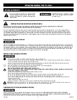
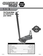
Page 1: ...Maximum Height 22 2 Ram Travel 9 Working psig 116 174 Adapters 1 7 and 3 Overall Width 11 1 Overall Length 31 7 Handle Length 54 3 Weight 160 6 lbs SPECIFICATIONS 25 50 Ton Air Truck Jack 791 9001 791 9001 S A FETY STANDA R D C OMPLIES IT H W ASME PASE 2014 ...

Page 2: ...ed modified in poor condition leaking hydraulic fluid or unstable due to loose or missing components Make corrections before using Use only on a hard level surface free from obstructions so the jack is free to reposition itself during lifting and lowering operations Lift only on areas of the vehicle as specified by the vehicle manufacturer User and bystanders must wear eye protection that meets AN...

Page 3: ... lever 106 to the right Lowering the ram is accomplished by rotating the lever to the left b The saddle 99 has a hole in it to receive the adapters 75 The adapters can be stacked on top of each other for additional height Evaluate the work to be done to determine if there is enough ram stroke to lift the load Adding adapters can bring the jack closer to the load so you can get more effective ram s...

Page 4: ...raulic repairs within the warranty period must be performed by an authorized service center INSPECTION Visual inspection should be made before each use of the jack checking for leaking hydraulic fluid and damaged loose or missing parts Each jack must be inspected by a manufacturer s repair facility immediately if subjected to an abnormal load or shock Any jack which appears to be damaged in any wa...

Page 5: ...9 20 21 22 23 24 25 26 27 28 37 38 39 40 41 42 43 44 45 46 47 48 49 50 51 52 53 54 55 56 57 58 60 61 62 63 64 65 66 67 01 02 03 04 05 06 07 08 09 10 11 13 59 12 29 30 31 32 33 34 35 36 RS900102 Pump Assembly RS900101BK Oil Cylinder Assembly RS900104BK Handle Assembly ...

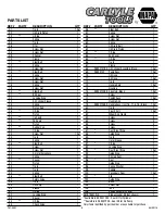
Page 6: ...Spring 1 58 Screw Nut 1 59 Screw Nut 1 60 Spring 1 61 Oil Drain Bolt 1 62 Oil Drain Piston 1 63 O Ring 2 64 End Cover 1 65 O Ring 1 66 Tie In 1 67 Clamp 1 68 RS900101BK Oil Cylinder Assembly Black 1Set 69 RS900102 Pump Assy 1Set 70 Oil Hose 1 71 Air Hose 1 Set 72 Tie In 4 73 Handle Sets 1 Set 74 Housing 1 75 RS900103BK Adaptors Black 1 Set 76 Screw 1 77 Switch Assy 1 Set 78 Handle Grip 1 79 RS9001...

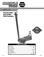
Page 7: ... máxima 22 2 Recorrido del eje 9 PSIG de trabejo 116 174 Adaptadores 1 7 y 3 Anchura global 11 1 Longitud global 31 7 Longitud del mango 54 3 Peso 160 6 libras ESPECIFICACIONES 791 9001 Gato Neumático para Camión 25 50 Toneladas S A FETY STANDA R D C OMPLIES IT H W ASME PASE 2014 ...

Page 8: ...tampoco si presenta inestabilidad debido a piezas metálicas o partes desajustadas o faltantes Tome las medidas de corrección apropiadas antes de usarlo Use el gato únicamente en superficies niveladas firmes en las que no haya obstáculos de modo que el dispositivo pueda posicionarse durante las operaciones de elevación y descenso Utilice el dispositivo de elevación únicamente en las áreas del vehíc...

Page 9: ...versa sobre las INSTRUCCIONES DE USO con el fin de advertir sobre los peligros de accidentes personales Observe todas las instrucciones para evitar lesiones o peligros de muerte IMPORTANTE antes de comenzar a elevar un vehículo consulte su manual de servicio para conocer las superficies de elevación recomendadas FORMA DE USO 1 Familiarícese con la identificación y función de los componentes del ga...

Page 10: ...n donde no quede expuesto a las condiciones climáticas gases corrosivos sustancias abrasivas u otros materiales perjudiciales Previo al uso este gato deberá estar limpio de agua nieve arena gravilla aceite grasa o cualquier otro material ajeno 2 El gato deberá ser lubricado periódicamente con el fin de prevenir el desgaste prematuro de las partes Una grasa de uso general deberá aplicarse al eje al...

Page 11: ... capacidad nominal no deberá más de 1 8 3 18mm en el primer minuto ni un total de 1875 4 76mm en 10 minutos Bajar dentro de este rango se considera como una operación normal y NO es un defecto garantizable RESPONSABILIDAD DEL PROPIETARIO USUARIO El propietario y o usuario debe contar con una comprensión de las instrucciones y advertencias de operación del fabricante antes de usar este gato El pers...

Page 12: ... 9 po Pression de service psig 116 174 Adaptateurs 43 1 cm 7 6 cm 1 7 po et 3 po Largeur totale 281 9 cm 11 1 po Longueur totale 805 2 cm 31 7 po Longueur de la poignée 135 6 cm 54 3 po Poids 72 8 kg 160 6 livres SPÉCIFICATIONS 791 9001 791 9001 Cric Pneumatique de 25 50 Tonnes pour Camion S A FETY STANDA R D C OMPLIES IT H W ASME PASE 2014 ...

Page 13: ...ndommagé modifié en mauvais état instable en raison de pièces ou de quincaillerie manquantes ou lâches ou s il y a fuite de fluide hydraulique Effectuer les réparations ou les réglages nécessaires avant l utilisation Utiliser le cric seulement sur une surface de niveau et solide Celle ci doit être exempte d obstructions afin que le cric puisse se repositionner durant le levage et la descente Place...

Page 14: ...droite Tourner le levier vers la gauche permet d abaisser le vérin b La selle 99 a un orifice lui permettant d y insérer les adaptateurs 75 Les adaptateurs peuvent être empilés les uns sur les autres pour y ajouter de la hauteur Évaluez le travail à effectuer afin de déterminer s il y a suffisamment de course dans le vérin pour soulever la charge En ajoutant les adaptateurs on rapproche le cric de...

Page 15: ...es par la garantie 3 Il n est pas nécessaire de remplir ou de rajouter du fluide hydraulique dans le réservoir sauf si une fuite externe est détectée En cas de fuite externe alors que le cric est toujours sous garantie rapporter le cric dans n importe quel magasin pour une réparation ou un remplacement sous garantie IMPORTANT Pour prévenir les dommages aux joints d étanchéité et la défectuosité du...

Page 16: ...icules et de leurs composantes On devrait insister particulièrement sur la compréhension des renseignements touchant les mises en garde Si l utilisateur ne parle pas couramment l anglais les directives du manufacturier et les mises en garde devraient être lues et discutées par l acheteur propriétaire avec l utilisateur dans sa langue maternelle pour s assurer de la bonne compréhension du contenu p...

Reviews: