17
Accelaterm
®
Installation and Service Manual
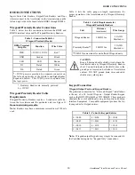
Magnetic Stripe Reader Connection
Magnetic Stripe Readers (
not evaluated by UL
) connect to
terminal strips DR (see Figure 10).
Note:
Magnetic Stripe readers are normally powered by
5VDC, and must use the separate 5VDC Accessory Power
Connections provided.
Table 6 lists the connections between the DR1 and DR16 ter-
minal strips and the Magnetic Stripe Reader.
Magnetic Stripe Reader Cable Requirements
Magnetic Stripe Readers require a 5-conductor cable between
the Accelaterm and the particular unit (see Figure 10).
Do not
use twisted pair cable.
Table 7 lists the cable gauge-vs.-length requirements for
proper operation of the Accelaterm and Magnetic Stripe Read-
ers.
CAUTION
Keep all drain wires between the Accelaterm
and Magnetic Stripe Readers short. Connect
drain wires to the ground posts located on
both sides of Accelaterm cabinet. DO NOT
ground drain wires and cable shields at any
other point.
DOOR CONNECTIONS
Table 6 - Connection Table for Magnetic Stripe
Reader
DRx Terminal Strip Pin
Function
(Not used, see Note)
+5VDC (Red)
(Not used, see Note)
Ground (Black)
LED (Brown)
LED
1
(Yellow)
D1 (White)
Data-1/DAT (Blue)
D0 (Green)
Data-0/CLK (Green)
Note 1:
If the Magnetic Stripe Reader does not feature
an LED indicator, 4-conductor cable may be used.
Unit
Distance
Wire Gauge
Magnetic Stripe
Reader
(maximum)
500ft/153m
22AWG Shielded
w/drain
Table 7 - Cable Requirements for Magnetic Stripe
Reader
Figure 10 - Magnetic Stripe Reader Connection to Accelaterm Board
PWR
GND
LED
D1
D0
DS
RT
REX
RT
Magnetic Stripe Reader
Accelaterm Circuit Board
Terminal
Strip
DR1-
DR16
Brown
White
Green
Drain Wire/Shield
Accelaterm Cabinet Ground Post
GN
D
(
B
la
ck
)
RD
P (
B
lu
e)
RCP (Green)
+5V
(
R
ed
)
LED
(
Y
ello
w
)
Re
d
Bl
ack
Br
ow
n
Wh
ite
Green
500 feet Wire (Max)
+5V
-5V

