Accelaterm
®
Installation and Service Manual
18
Door Status Sensor Connection
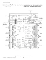
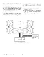
Door Status sensors connect to the Accelaterm through two ter-
minal strips labeled RDRx (see Figure 11).
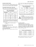
Table 8 lists the connections between the RDRx terminal strips
and the Door Status sensor.
Door Status Sensor Cable Requirements
Door Status sensors require a 22AWG, 2-conductor, stranded,
shielded, cable with drain wire between the Accelaterm and the
particular unit (see Figure 11).
Table 9 lists the cable gauge-vs.-length requirements for proper
operation of the Accelaterm and the Door Status sensor.
NOTES:
Refer to page 24, Accessory Alarm Connections, to
configure Door Status sensors as supervised alarms.
The Door Status sensor is normally used to turn off the lock
after the door is closed. It also senses if the door was forced
open (triggers a Door Forced Alert at the Host Computer at the
central station).
DOOR CONNECTIONS
CAUTION
Keep all drain wires short. Connect drain wires to the ground posts located on both sides of Accelaterm
cabinet. DO NOT ground drain wires and cable shields at any other point.
Table 8 - Connection Table for Door Status Sensor
RDRx Terminal
Strip Pin
Signal
Door Status
Sensor Function
DS
Alarm
Positive
RT
Return
Negative
Table 9 - Cable Requirements for Door Status Sensor
Unit
Distance
Wire Gauge
Door
Status Sensor
500ft/153m
22AWG Shielded
w/drain
Figure 11 - Door Status Sensor to Accelaterm Connections. Plain (Unsupervised) Contacts, and Supervised Contacts
Accelaterm Circuit Board
Drain Wire/
Shield
PWR
GND
LED
D1
D0
DS
RT
REX
RT
PWR
GND
LED
D1
D0
DS
RT
REX
RT
Accelaterm Cabinet
Ground Post
Unsupervised Door
Status Sensor
Drain Wire/
Shield
Accelaterm Cabinet
Ground Post
Supervised Door
Status Sensor
R1=1K
R2=1K


