18 Gemini C-Series GEMC-NAC Extender Installation Instructions
6. PREPARING THE GEMC-NACXX PC BOARD
Item
Part No.
Description
QTY
1
PCB
GEMC-NACXX PC Board
1
2
SI178
Fishpaper
1
3
HW1829
Mounting Button
2
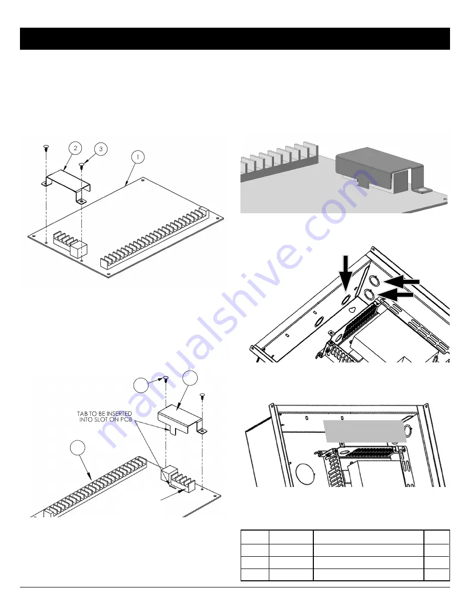
A small folded fishpaper must be installed over the power
terminals to electrically isolate the terminals and serve as
an electrical barrier to ensure against accidental contact
with high voltage wiring.
Note:
This Fishpaper is only re-
quired for non-power limited wiring (i.e. 120VDC). Install
the fishpaper as follows:
MOUNTING AND INSTALLATION (CONT'D)
FISHPAPER AND TWO MOUNTING BUTTONS
SEE TABLE BELOW FOR NUMBER DESCRIPTIONS
1.
Orient the SI178 Fishpaper
(item 2 in the illustration be-
low) over the GEMC-NACXX power terminals such that
the fishpaper tab is aligned with the slot in the GEMC-
NACXX PC board. This slot is located next to the termi-
nals (see illustration below).
FISHPAPER ORIENTATION AND INSTALLATION
SEE TABLE AT RIGHT FOR NUMBER DESCRIPTIONS
3
2
1
POWER
TERMINALS
FINISHED FISHPAPER INSTALLATION
2.
Insert the SI178 Fishpaper tab
into the GEMC-NACXX
PC board slot. Ensure the two mounting holes in the
Fishpaper align with the mounting holes in the GEMC-
NACXX PC board.
3.
Insert the two HW1829 Mounting Buttons
into the two
mounting holes. Press the Mounting Buttons firmly to
secure.
The finished installation is shown in the image below.
USE KNOCKOUTS (ARROWS) FOR WIRING NON-POWER
LIMITED WIRING TO RELAY 7
(L
EF
T
SI
DE
)
(TO
P)
GRAY SHADED AREA IN ABOVE IMAGE: KEEP ALL POWER LIMITED
WIRING OUTSIDE GRAY SHADED AREA WHEN RELAY 7 IS USED TO
SWITCH NON-POWER LIMITED CIRCUITS.
(LEFT SIDE)
(T
O
P
)


