background image

L

 NAPCO Security Systems  

X


GEM-P3200 Installation Instructions 

WI817F  10/05 


Page 29


function), or autoarming may be canceled by arming and disarming the panel. 


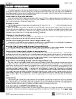
ACTIVATE PROGRAM 

At Keypad No.  1, press the YES button to activate the User Program (Program-1) Mode or Dealer Program (Program-2) 

Mode, depending upon the code entered.  Scroll through the programmable functions using NEXT the button and PRIOR the 
button.  To exit this mode at any time, press 

CC

.  

Note:

  Keypad No. 1 may be located in any area. 


ACTIVATE DOWNLOAD 

Used on-site for remote downloading of a control-panel program from the PCD-Windows.  Press the YES button to initiate 

the data transfer. 


DISPLAY RF XMITTER STAT 

Press the YES button to check the status of up to 48 transmitters.  The keypad will display: 

zone number (Z01-Z48) 

transmitter ID code number (6 digits) 

point number (PT1-PT4; "9" for unsupervised) 

status of transmitter: 


NODATA:  

transmission not yet received 


NORMAL:  

transmitter's zone normal; 


FAULT:  

transmitter's zone open; 


LOBATT:  

transmitter battery low; 


TAMPER:  

transmitter case open; 


S.FAIL:  

supervisory failure (test transmission not received within programmed time); 


relative signal strength of the last transmission, on a scale of 1-10 (10 being the strongest).  ("SS—" indicates trans-

mission not yet received).  

Note:

  A signal strength of 3 or less is an indication that reception may be unreliable.  In such 

cases, the use of an additional receiver located closer to the transmitter is recommended.  If two receivers are connected to 
the GEM-P3200, only the higher signal strength of the two will be displayed. 


RELAY CONTROL 

Press the YES button to check the status (all on or all off) of up to 2 groups programmed with any combination of up to 24 

available external relays.  The group number will display with a related description.  Scroll through the groups using the NEXT 
and PRIOR buttons; change the status of the displayed group by pressing the 

U

 button. 

B

A

SIC OPER

A

T

IO

Summary of Contents for Gemini GEM-P3200

Page 1: ...RP3DGTL and GEM RP4RFC GEM RP4C and with K Series keypads GEM K1CA GEM K2AS GEM K3DGTL and GEM K4RF GEM K4 Publicly traded on NASDAQ Symbol NSSC K Series GEM K1CA G E M I N I SYSTEM READY 01 01 06 12...

Page 2: ...ol panel zones 7 8 Page 18 also removed the incorrect wiring diagram and accompanying text THIS MANUAL INCLUDES FEATURES WHICH ARE ONLY AVAILABLE IN CONTROL PANEL FIRM WARE VERSION 50 OR LATER NAPCO S...

Page 3: ...oth keypads The words NEXT YES button are used in this manual The button and the button operate identically in Program Mode for both keypads The words PRIOR NO button are used in this manual For consi...

Page 4: ...figuration 16 4 Wire Smoke Detectors 17 2 Wire Smoke Detectors 17 Telephone Lines 18 KEYPAD CONFIGURATION MODE 19 Keypad Installation 19 Configuring the Keypads 19 BASIC OPERATION 22 User Codes Zone D...

Page 5: ...downloaded to the control panel using a PC compatible computer with NAPCO s PCD Windows Quickloader software and a PCI2000 computer interface Or the panel may be programmed using the keypad in its sec...

Page 6: ...ID Rotary dial TouchToneTM only and TouchToneTM with Rotary backup Three 20 digit telephone numbers Backup Reporting Double Reporting Split Reporting 48 User Codes with Open Close Reporting by user AC...

Page 7: ...EM RP3DGTL GEM K3DGTL 50 mA GEM RP4RFC GEM K4RF 75mA Standby GEM RP4C GEM K4 45mA Standby PGM Output 5mA 12V Special Application Maximum Number of Keypads 7 Maximum Wiring Length for each run 22AWG 10...

Page 8: ...le plug in 20 OI193 User Guide GEM RP1CAe2 OI192 User Guide GEM RP2ASe2 OI249 User Guide GEM RP3DGTL OI278 User Guide GEM RP4C RP4RFC WI1212 Installation Manual GEM RP4C WI1128 Installation Manual GEM...

Page 9: ...rogrammed for Priority Do not program any zones for Keyswitch Arming System must be serviced at least once every year Residential Fire and Combination Residential Fire Burglary must program Residentia...

Page 10: ...ew The sole purpose of the self tapping screw is to tap the holes for the machine screws it may be discarded after use Keypad A keypad should be located near each exit entry door The keypad features a...

Page 11: ...than those required such as the dining room bed rooms utility room furnace room and hallways Heat detectors rather than smoke detectors are recommended in kitchens at tics and garages due to condition...

Page 12: ...Ademco 7720 Long Range Wireless System The RM3008 may be used to interface the GEM P3200M control panel to the Ademco 7720 transmitter in order to meet UL Central Station Grade A or Grade B requireme...

Page 13: ...ansmitter to be tested by faulting the zone The transmitter signal strength can be displayed using the DISPLAY RF XMITTER STAT function Enter a Level 3 User Code or enter the Dealer Code press the A b...

Page 14: ...T 1 2 The RED and BLACK flying leads must be connected to a 12VDC 4 6 or 7 AH Rechargeable Battery to serve as backup power in the event of AC Power Failure NOTE To calculate the available standby tim...

Page 15: ...tance for seven keypads is 300 feet using 22 AWG wire NOTE When running keypad wire avoid wiring parallel to other types of wiring that can cause electrical interference WIRING CONNECTIONS REMOTE BUS...

Page 16: ...selected see GEM P3200 Programming Instructions Connect the device controlled by the programmable output between terminal 15 and terminal 14 15 RESET OUTPUT EXPANDED ZONE CONFIGURATION The GEM P3200...

Page 17: ...d to any programmed fire zones 9 32 Do not use in UL installations See page 9 Power must be obtained from terminal 28 and 29 If Fire Alarm Verification is de sired to reset the smoke detectors select...

Page 18: ...ack or a CA31A jack for Canadian installations The Telco Line is used by the control panel to dial the central station and for downloading This line should not be connected to party lines or coin oper...

Page 19: ...pad must be configured for a keypad tactile beep b entry sounder c keypad address d EZM address and e zone response To enter the GEM RP1CAe2 GEM K1CA Configuration Mode 1 Move jumper JP1 located at th...

Page 20: ...ZMs it must be assigned a unique address or Group number see Keypad Programming Workbook similar to its keypad address If no other EZMs are to be used designate the keypad as Group 01 at the EZM ADDRE...

Page 21: ...be selected as Keypad 1 Assign the keypad address number by selecting Jumpers J1 3 in accordance with the ta ble at left Note 1 Keypads are factory supplied with no jumpers in stalled and as such are...

Page 22: ...ode only A Service Code is an Arm Disarm Code that is easily activated when needed and dormant at other times Intended for the occasional or temporary user repairman etc who would otherwise be denied...

Page 23: ...EM RP1CAe2 GEM K1CA keypads only An S in the display e g EXIT TIME XXX S will appear as a re minder that the system is being armed with the Service Code active To turn off the Service Code disarm then...

Page 24: ...an Auto Arm a User can press the R or A button until TO DE LAY AUTO ARM PRESS 1 4 N is displayed Enter the number of hours to delay arming followed by the U or D button If DELAY AUTO ARM Y N is displ...

Page 25: ...number The zone will be unbypassed the next time the system is disarmed Security Bypass Zones programmed for Selective Bypass may be removed from the system prior to arming as follows 1 Enter a code...

Page 26: ...le to the user s authority level will be suppressed and will not display 2 Press the PRIOR NO button to skip a function press the NEXT YES button to execute it 3 The GEM RP2ASe2 GEM K2AS displays abbr...

Page 27: ...if programmed permits all zones designated as Day Zones to be turned on When selected a W will appear in the display GEM RP1CAe2 only as long as the Watch Mode is active To deactivate the Watch Mode...

Page 28: ...K3DGTL Keypads Displays most recent openings and closings Line 1 displays event and date Line 2 displays time area and user To check previous events scroll back using the PRIOR button DISPLAY SYSTEM L...

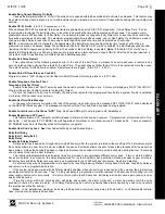
Page 29: ...status of transmitter NODATA transmission not yet received NORMAL transmitter s zone normal FAULT transmitter s zone open LOBATT transmitter battery low TAMPER transmitter case open S FAIL supervisory...

Page 30: ...number E07 00 DOWNLOAD FAIL Download failure E08 00 TELCO LINE1 FAIL Telephone line failure system trou ble displays after a programmed delay E09 00 NOT PROGRAMMED System cold start E10 NNN KEYPAD AC...

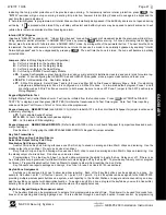
Page 31: ...n Access on Aux Output into the Aux 1 or Aux 2 option locations on the Wire less KeyFobs screen This feature also requires a valid time to be entered into the Aux Output Access Control in the Time Sel...

Page 32: ...report to be sent to a cen tral station Thus should a user be forced to disarm he can silently signal an emergency while appearing to be merely disarming the system The Ambush Zone will automatically...

Page 33: ...assed Note A zone in trouble that is not programmed for Auto Bypass will cause an alarm on arming after a 10 second arming delay If Auto Bypass Re entry is selected securing a zone that is programmed...

Page 34: ...s The feature 2nd Call Answering Machine Override allows downloading after 1 the panel detects 1 or 2 rings 2 the panel does not detect another ring for 8 seconds 3 the panel detects another ring with...

Page 35: ...Identification Number is 6789 the Closing Code is C The communicator will send the following report to the central station When alarm occurs 6789 35 Alarm Zone 5 Closing Report 1234 C1 Closing User 1...

Page 36: ...niversal High Speed Ademco 685 Formats Ademco Slow Silent Knight Slow Silent Knight Fast Sescoa Vertex DCI Franklin Slow Franklin Fast Radionics Slow Radionics Fast Radionics BFSK Universal High Speed...

Page 37: ...e report a Ring Back will be given Digital Dialer Test Activating the digital dialer test from the Function Menu ACTIVATE DIALER TEST will send the programmed report code to the central station Progra...

Page 38: ...d properly Any program changes such as adding changing user codes adding users to an area or changing Entry Exit Delays will be processed properly with the panel armed Don t Clear Aux Relay with Arm D...

Page 39: ...activated A minimum of 30 seconds is recommended Enable Set Time Date Message In the event of a memory corruption the loss of the system clock will occur and a message SET TIME DATE will be displayed...

Page 40: ...e detector A short across the zone will cause a fire alarm which will be indicated at the keypad by a FIRE LCD display and pulsing sounder An open circuit on the Fire Zone will identify a trouble and...

Page 41: ...l DIGITAL DIALER TEST Y N is displayed and then press NEXT YES to initiate the transmission of a Test Timer signal Note Test Timer reporting codes and Report Test Timer on Telco1 or Telco 3 must be pr...

Page 42: ...e zone and 1234 is the Subscriber ID number If the Leading Digits are programmed as 98 1st digit Address Location 0520 y 9 2nd digit Address Location 0521 y 8 the Pager report will now appear as 983 0...

Page 43: ...ystem RAM fail only the Master Security Code will work The Dealer Security Code is needed to enter the Dealer Program Mode thus allowing the dealer to program codes zone fea tures reporting features a...

Page 44: ...econds Pre Dial Delay A Pre Dial Delay may be used whenever a delay is required before dialing It may be required when programming Dial Tone De tection which causes the communicator to wait before it...

Page 45: ...signing or mapping events to relay numbers PCD Windows must be used to program Relay X 10 mapping Referring to the PCD Windows External Relay Control screen the Relay Entry column typically indicates...

Page 46: ...is expected This feature supervises the sensor by verifying that the zone activates before the PIR timer runs out If no trip is de tected within the programmed Sensor Watch time a system trouble will...

Page 47: ...t Telco 3 Start Exit Delay After Ringback When a closing report is successfully received the central station will acknowledge by returning a kissoff signal When the kis soff is received by the communi...

Page 48: ...panel leaves the factory with no zones programmed for Auto Reset If Enable CP 01 Features is selected in the Easy Programming menu all non fire zones will not be programmed for Auto Reset System Troub...

Page 49: ...3 is programmed for Double or Split Reporting Private telephone systems may require a Dial Tone Detection E or Pre Dial Delay D followed by an access number to obtain an outside line See Access Numbe...

Page 50: ...elected the communicator will alternate between TouchTone and rotary dial to reach Telephone 1 then Telephone 2 See Backup Report on Telco 2 Trouble An abnormal zone condition a break in a normally cl...

Page 51: ...ess Byte The Authority Level comprises an Option Code Refer to Programming Manual WI818 or WI1184 for descriptions of levels and options If reporting to a central station program User Closing and Open...

Page 52: ...ntire Group If Enable Local Alarm on First ZoneAND Trip Address 2419 is programmed a trip on any Zone of the Group will cause an alarm output and alarm display at the keypad there will be no communica...

Page 53: ...QTY EACH TOTAL GEM P3200 1 X 0 120 GEM EZM4 8 X 0 050 GEM EZM8 X 0 050 GEM RP1CAe2 GEM K1CA X 0 100 GEM RP1CAe2 GEM K1CA 1 X 0 035 GEM RP2ASe2 GEM K2AS X 0 065 GEM RP2ASe2 GEM K2AS 2 X 0 020 GEM RP3DG...

Page 54: ...ecessary use this wiring legend to relocate wire leads to their proper terminals Enter wire identification number or color code in WIRE NUMBER column and enter wire function in DESCRIPTION col umn opt...

Page 55: ...IEW 3 B ACTIVATE CHIME 1 ACTIVATE WATCH 2 RESET SYSTEM TRBL 3 RESET SENSOR MSG 3 START EXIT TIME 1 FAULT FIND C ACTIVATE LOCATE C EZM ZONE FIND C FUNCTION LEVEL A ACTIVATE DIALER TEST 3 DISPLAY ALARM...

Page 56: ...TIVATE OVERVIEW 3 B ACTIVATE CHIME 1 ACTIVATE WATCH 2 RESET SYSTEM TRBL 3 RESET SENSOR MSG 3 START EXIT TIME 1 FAULT FIND C ACTIVATE LOCATE C EZM ZONE FIND C FUNCTION LEVEL A ACTIVATE DIALER TEST 3 DI...

Page 57: ...TER ZONE XX E CHIME ZONES ENTER ZONE XX E CHIME 2 ZONES ENTER ZONE XX E EXIT ENTRY 2 ZNS ENTER ZONE XX E 50MS LOOP ZONES ENTER ZONE XX E AUX OUTPUT ZONES ENTER ZONE XX E SENSOR WATCH ZNS ENTER ZONE XX...

Page 58: ...X GEM P3200 Installation Instructions L NAPCO Security Systems WI817F 10 05 Page 58 NOTES...

Page 59: ...t about 15 seconds 01 OUT OF SYSTEM JP5 is located at the top right corner of the circuit board If a Compatibility Number other than 0000 is programmed OLD COMPAT XXXX is displayed KEYPAD PROGRAMMING...

Page 60: ...X GEM P3200 Installation Instructions L NAPCO Security Systems WI817F 10 05 Page 60 GEM P3200 WIRING DIAGRAM...

Page 61: ...d minimum default is 30 seconds If an attempt is made to change the Entry Delay time to less than 30 seconds the time will be entered as 30 seconds The maximum programmable time is 255 seconds The pan...

Page 62: ...ted at address 0887 Keypad will display the following warning that the system is in Fault Find FAULT FIND RF SIG POWER If a 24 hour zone is tripped and not restored during Fault Find when the mode is...

Page 63: ...All zones are programmed with report codes and as burg fire alarm types depending on whether they were selected as fire zones Zones not selected as fire are burg type 5 The reporting format is selecta...

Page 64: ...connect the equipment Users should ensure for their own protection that the electrical ground connections of the power utility telephone lines and internal metallic water pipe system if present are co...

Page 65: ...ssary the user should consult the dealer or an experienced radio television technician for additional suggestions The user may find the following booklet prepared by the Federal Communications Commiss...

Page 66: ...X GEM P3200 Installation Instructions L NAPCO Security Systems WI817F 10 05 Page 66 Notes...

Page 67: ...L NAPCO Security Systems X GEM P3200 Installation Instructions WI817F 10 05 Page 67 Notes...

Page 68: ...ther assumes nor au thorizes any other person purporting to act on its behalf to modify to change or to assume for it any other warranty or liability concerning its products In no event shall NAPCO be...

Reviews: