of 6
7/17/99
WI988
4
PHASTLink Cable Information
This section contains information that you will need to make PHASTLink cables, plus general information on
connecting PHASTLink devices.
PHASTLink cables are used to connect all PHASTLink-compatible devices, including keypads, dimmers, J-box IR
devices, amplifiers, audio switches, etc.
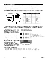
PHASTLink uses a standard 10Base-T connection (i.e. Category 5 wire and RJ-45 connectors). The wire should be
connected in the standard manner, as shown in the following figure. If a consistent color code is used, wiring
problems will be minimized.
Pin #
Wire Color
Polarity
Function
1
White/Green
+
Transmit
2
Green
–
Transmit
3
White/Orange
–
Mic
4
Blue
–
Ground
5
White/Blue
+
12VDC
6
Orange
+
Mic
7
White/Brown
+
Receive
8
Brown
–
Receive
It is important that the correct pairing is observed. Transmit, receive, and mic need to be on twisted pairs. Splitting
pairs (e.g., using a white/green wire with a blue/white wire for transmit) will result in increased crosstalk, and may
result in bus failure or noise on the intercom.
If a PLB-CF10 cardframe is used, a 15-port
hub is built into the cardframe. The maximum
length of wire per port is 1,000 feet. Each
PHASTLink device has two RJ-45 connectors
to allow multiple devices to be daisy chained
on one PHASTLink port. Refer to the PLB-
CF10 documentation for more detailed
connection information.
The limit for each home run is 10 PHASTLink
devices. Extra hubs can be added to provide
additional ports.
Note:
Only one PHAST keypad can be used
per port, so home-run each keypad.
For optimum performance, PHAST
recommends the installation of a double 120-
ohm terminator in one of the RJ-45 jacks of
the last device (or the only device) in a chain
of PHASTLink devices.
To build a double 120-ohm terminator:
a.
Install a 120-ohm resistor (1/4-watt or larger) between pins 1 and 2 of an RJ-45 connector.
b.
Install a 120-ohm resistor (1/4-watt or larger) between pins 7 and 8 of the same RJ-45 connector.
1
1
2
2
3
3
4
4
5
5
6
6
7
7
8
8
RJ-45 Socket
RJ-45 Plug


