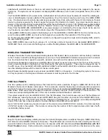
NAPCO Gemini C-Series Control Panel Installation Instructions--Volume 2
Page 16 Installation Instructions, Volume 2
provides two unsupervised independently configurable Form C relay contacts per address, and the FWC-FSLC-
SOM1 Supervised Output Module provides a single supervised NAC output (or NAC01-40 on the GEMC-NACXX
which requires a UL 1481 Listed Regulated 24V power supply, properly installed, to power the output). See
WI1821 for additional information.
The GEMC-FW-SLC can act like virtual relay boards 1-5, allowing up to a maximum of 40 FWC-FSLC-SOM1's or
FWC-FSLC-RM2's on the GEMC-FW-SLC. The SOM / RM2 must be programmed with a FWC-FSLC-PROG2
Programmer as 126 to 102. (The progression is as follows: 126 is Relay #1, 125 is relay #2 … 103 is relay #24).
Note:
If two relays are added to the FWC-FSLC-RM2, the second relay must be mapped to the same (virtual)
relay board as the first relay.
SPECIAL NOTE: FWC-FSLC-SOM1
To prevent a single break, single ground, or wire-to-wire fault on the installation conductors of a signaling line circuit for use
with addressable notification appliances or modules shall not affect operation of more than one notification zone, the following
is required when using more than one FWC-FSLC-SOM1 on an SLC loop:
1. The SLC must be configured and programmed as grade A style 7, and
2. The Regulated 24VDC power circuit must either be wired from different circuits, or when circuits are shared, must be
protected with rigid conduit or other suitable method.
3. To ensure survivability from attack of both the SLC and power circuits, the installation must meet or exceed the
Path-
way Survivability Levels
1-3 as described in NFPA 2010 edition, clauses 12.4.2, 12.4.3 and/or 12.4.4.
Each Fire SLC can have all 5 relay boards enabled, but the system can not have duplicate relay board numbers
on the same or different busses (Burg 4-wire bus, Burg SLC bus, Fire 4-wire bus or other devices on the Fire
SLC bus).
To be used in the system, the FWC-FSLC-RM2 and the FWC-FSLC-SOM1 must be pre-programmed prior to in-
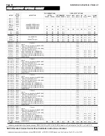
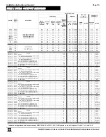
stallation to the correct address using the FWC-FSLC-PROG2 hand held programming tool. The address (126-
187) is determined by the number of the External Relay as directed by the "
FIRE OUTPUT RELAY CHART
" fur-
ther in this manual. . In addition, the selected module must also be configured for the correct relay group (1-8)
using the
RELAY
dip-switch located on the module PC board.
For more information, see WI1715 (FWC-FSLC-RM2 installation instructions) and WI1717 (FWC-FSLC-SOM1
installation instructions).
Note:
Only one FWC-FSLC-SOM1 may be installed per SLC loop unless the system is configured and wired as
SLC loop Class A Style 7.
MAPPING ZONES TO OUTPUTS
Every Fire Zone must be programmed ("mapped") to at least one NAC, and may be programmed to activate mul-
tiple outputs. "Mapping" may be performed in one of two ways:
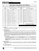
Method 1:
Fire zones may be mapped to motherboard terminals
NAC A
-
NAC D
or to external NAC’s 1-8 by
zone using PCD-Windows Quickloader. In the "
Workspace
", click
Feature View
to open the
Feature View
screen, click the output(s) for each Zone (to select, click the intersecting row/column "dot", then press the key-
board spacebar and a "
Y
" appears).
Method 2:
Fire zones may also be mapped using the
NAC/Output Assignments
screen,
NAC/Output Events
tab:
For a selected Output enabled in the
NAC/Output Assignments
screen, click the
NAC/Output Events
tab to
map the selected output to a particular event or combination of events. Notice the
NAC/Output Events
tab
contains rows and columns; in an unused row, select the Output in the
Relay #
column pull-down list, then
click in the
Event \ Alarm Type \ Condition
column for that row, and the
Relay Event
dialog opens. Note that
as events in this screen are clicked and highlighted, the
Relay Event
dialog changes to suit the nature of the
event, with
Alarm Type
and/or
Condition
fields appearing that also change as their attributes are selected.
For every zone programmed to initiate the event type selected (for example, "Area 1 Gen. Alarm") that zone
(or zones) are now mapped to that particular relay output.
Note:
Waterflow alarms are a subset of Fire Alarm
zones, therefore Waterflow and Fire alarm zones may activate the same outputs.
Outputs may not have different
Alarm
or
Trouble
conditions trigger the same output:
A particular Output may not share two or more Conditions (such as an Alarm and a Trouble Condition) simulta-
neously.
1. Outputs programmed to activate on a
Fire Alarm
may not also activate on a
Supervisory
alarm,
Fire
Trouble
condition or non-Fire related change of state.
2. Outputs programmed to activate on a
Supervisory
may not activate on
Fire Alarm Fire Trouble
or non-

