background image

NAPCO Gemini C-Series Control Panel Installation Instructions--Volume 2 

Installation Instructions, Volume 2                                                                                                                         Page 19 

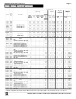
OUTPUT 

Dealer 

Entered 

Name 

OUTPUT TYPE 

OUTPUT DEVICES  

GEMC-FW-SLC 

GEMC-BSLC 

GEMC-OUT8  

or 

GEMC-RM3008


GEMC-FW-

SLC RELAY 

DIP SWITCH 

SETTING 

IS DEVICE 

SOM? 

Y/N 

IS DEVICE 

1st relay of 

RM2? 

Y/N 

IS DEVICE 

2nd relay of 

RM2? 

Y/N 

FWC-FSLC-

SOM1 OR  

FWC-FSLC-

RM2  

PRO-

GRAMMED 

ADDRESS 

GEMC-BSLC 

RLY 

SWITCH 

GEMC-

BSLC-RLY 

Dial ADD. 

JUMPER 

ADD. 

OUTPUT # 

NAC ADDR 

Shunts 

OUTPUT # 

NAC A 

PNCA- 

Integral GEMC-255MB outputs 
Integral GEMC-128MB outputs 

Integral GEMC-96MB outputs 

Integral GEMC-32MB outputs 

N/A 

N/A 

N/A 

N/A 

N/A 

N/A 

N/A  N/A 

N/A 

N/A 

N/A 

N/A 

NAC B 

PNCB- 

N/A 

N/A 

N/A 

N/A 

N/A 

N/A 

N/A  N/A 

N/A 

N/A 

N/A 

N/A 

NAC C 

PNCC- 

N/A 

N/A 

N/A 

N/A 

N/A 

N/A 

N/A  N/A 

N/A 

N/A 

N/A 

N/A 

NAC D 

PNCD- 

N/A 

N/A 

N/A 

N/A 

N/A 

N/A 

N/A  N/A 

N/A 

N/A 

N/A 

N/A 

FIRE AUX 

RELAY 

PFAR- 

N/A 

N/A 

N/A 

N/A 

N/A 

N/A 

N/A  N/A 

N/A 

N/A 

N/A 

N/A 

TROUBLE 

SOUNDER 

N/A 

N/A 

N/A 

N/A 

N/A 

N/A 

N/A 

N/A  N/A 

N/A 

N/A 

N/A 

N/A 

E7 

POE7- 

N/A 

N/A 

N/A 

N/A 

N/A 

N/A 

N/A  N/A 

N/A 

N/A 

N/A 

N/A 

E8 

POE8- 

N/A 

N/A 

N/A 

N/A 

N/A 

N/A 

N/A  N/A 

N/A 

N/A 

N/A 

N/A 

BURG BELL 

N/A 

Integral GEMC-BM  

or  

GEMC-BM/PS outputs 

N/A 

N/A 

N/A 

N/A 

N/A 

N/A 

N/A  N/A 

N/A 

N/A 

N/A 

N/A 

PGM1 

N/A 

N/A 

N/A 

N/A 

N/A 

N/A 

N/A 

N/A  N/A 

N/A 

N/A 

N/A 

N/A 

PGM2 

N/A 

N/A 

N/A 

N/A 

N/A 

N/A 

N/A 

N/A  N/A 

N/A 

N/A 

N/A 

N/A 

BURG 

RELAY 

N/A 

N/A 

N/A 

N/A 

N/A 

N/A 

N/A 

N/A  N/A 

N/A 

N/A 

N/A 

N/A 

EXT OUT 1 

EO01- 

Circle one: 

 None 

 Burg Output on 4-wire Burg Bus (BURG GEMC-

RM3008 or BURG GEMC-OUT8) 

 Fire Output on 4-wire Fire Bus (FIRE GEMC-

RM3008 or FIRE GEMC-OUT8) 

 Burg Output on Burg SLC 1 (GEMC-BSLC #1) 

 Burg Output on Burg SLC 2 (GEMC-BSLC #2) 

 Fire Output on Fire SLC 1 (GEMC-FW-FSLC #1) 

 Fire Output on Fire SLC 2 (GEMC-FW-FSLC #2) 

 GEMC-NACXX 


126 

NAC 1 

EXT OUT 2 

EO02- 


125 

NAC 2 

EXT OUT 3 

EO03- 


124 

NAC 3 

EXT OUT 4 

EO04- 


123 

NAC 4 

EXT OUT 5 

EOO5- 


122 

RLY OUT 5 

EXT OUT 6 

EO06- 


121 

RLY OUT 6 

EXT OUT 7 

EO07- 


120 

RLY OUT 7 

EXT OUT 8 

EO08- 


119 

N/A 

EXT OUT 9 

EO09- 

Circle one: 

 None 

 Burg Output on 4-wire Burg Bus (BURG GEMC-

RM3008 or BURG GEMC-OUT8) 

 Fire Output on 4-wire Fire Bus (FIRE GEMC-

RM3008 or FIRE GEMC-OUT8) 

 Burg Output on Burg SLC 1 (GEMC-BSLC #1) 

 Burg Output on Burg SLC 2 (GEMC-BSLC #2) 

 Fire Output on Fire SLC 1 (GEMC-FW-FSLC #1) 

 Fire Output on Fire SLC 2 (GEMC-FW-FSLC #2) 

 GEMC-NACXX 


118 

NAC 1 

EXT OUT 10  EO10- 


117 

NAC 2 

EXT OUT 11  EO11- 


116 

NAC 3 

EXT OUT 12  EO12- 


115 

NAC 4 

EXT OUT 13  EO13- 


114 

RLY OUT 5 

EXT OUT 14  EO14- 


113 

RLY OUT 6 

EXT OUT 15  EO15- 


112 

RLY OUT 7 

EXT OUT 16  EO16- 


111 

N/A 

EXT OUT 17  EO17- 

Circle one: 

 None 

 Burg Output on 4-wire Burg Bus (BURG GEMC-

RM3008 or BURG GEMC-OUT8) 

 Fire Output on 4-wire Fire Bus (FIRE GEMC-

RM3008 or FIRE GEMC-OUT8) 

 Burg Output on Burg SLC 1 (GEMC-BSLC #1) 

 Burg Output on Burg SLC 2 (GEMC-BSLC #2) 

 Fire Output on Fire SLC 1 (GEMC-FW-FSLC #1) 

 Fire Output on Fire SLC 2 (GEMC-FW-FSLC #2) 

 GEMC-NACXX 


110 

NAC 1 

EXT OUT 18  EO18- 


109 

NAC 2 

EXT OUT 19  EO19- 


108 

NAC 3 

EXT OUT 20  EO20- 


107 

NAC 4 

EXT OUT 21  EO21- 


106 

RLY OUT 5 

EXT OUT 22  EO22- 


105 

RLY OUT 6 

EXT OUT 23  EO23- 


104 

RLY OUT 7 

EXT OUT 24  EO24- 


103 

N/A 

EXT OUT 25  EO25- 

Circle one: 

 None 

 Burg Output on 4-wire Burg Bus (BURG GEMC-

RM3008 or BURG GEMC-OUT8) 

 Fire Output on 4-wire Fire Bus (FIRE GEMC-

RM3008 or FIRE GEMC-OUT8) 

 Burg Output on Burg SLC 1 (GEMC-BSLC #1) 

 Burg Output on Burg SLC 2 (GEMC-BSLC #2) 

 Fire Output on Fire SLC 1 (GEMC-FW-FSLC #1) 

 Fire Output on Fire SLC 2 (GEMC-FW-FSLC #2) 

 GEMC-NACXX 


102 

NAC 1 

EXT OUT 26  EO26- 


101 

NAC 2 

EXT OUT 27  EO27- 


100 

NAC 3 

EXT OUT 28  EO28- 


99 

NAC 4 

EXT OUT 29  EO29- 


98 

RLY OUT 5 

EXT OUT 30  EO30- 


97 

RLY OUT 6 

EXT OUT 31  EO31- 


96 

RLY OUT 7 

EXT OUT 32  EO32- 


95 

N/A 

EXT OUT 33  EO33- 

Circle one: 

 None 

 Burg Output on 4-wire Burg Bus (BURG GEMC-

RM3008 or BURG GEMC-OUT8) 

 Fire Output on 4-wire Fire Bus (FIRE GEMC-

RM3008 or FIRE GEMC-OUT8) 

 Burg Output on Burg SLC 1 (GEMC-BSLC #1) 

 Burg Output on Burg SLC 2 (GEMC-BSLC #2) 

 Fire Output on Fire SLC 1 (GEMC-FW-FSLC #1) 

 Fire Output on Fire SLC 2 (GEMC-FW-FSLC #2) 

 GEMC-NACXX 


94 

NAC 1 

EXT OUT 34  EO34- 


93 

NAC 2 

EXT OUT 35  EO35- 


92 

NAC 3 

EXT OUT 36  EO36- 


91 

NAC 4 

EXT OUT 37  EO37- 


90 

RLY OUT 5 

EXT OUT 38  EO38- 


89 

RLY OUT 6 

EXT OUT 39  EO39- 


88 

RLY OUT 7 

EXT OUT 40  EO40- 


87 

N/A 

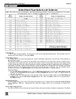
GEMC-NAC7S 
GEMC-NAC7L 

FIRE / BURG OUTPUT DEVICES 

 Indicates not applicable for all options except GEMC-NACXX or FWC-FSLC-SOM1 placed on a Fire Output on Fire SLC 1 or Fire SLC 2. 

Summary of Contents for GEMINI GEMC-255

Page 1: ...COMMUNICATOR Installing the GEMINI C Series Control Panels with the GEMC FK1 Keypad and the GEMC BK1 Keypad GEMC FK1 Keypad GEMC BK1 Keypad INSTALLATION INSTRUCTIONS VOLUME 2 R Publicly traded on NASD...

Page 2: ...d by implications or otherwise under any patent or patent rights of Napco Microsoft and Windows are registered trademarks of the Microsoft Corporation All other trademarks cited in this manual are for...

Page 3: ...C RM2 FWC FSLC SOM1 Devices 15 Mapping Zones to Outputs 16 Burglary Outputs 17 Fire Output Option Chart 18 Fire Burg Output Devices 19 Fire Glossary 21 37 Burglary Glossary 38 62 CP 01 Quick Reference...

Page 4: ...Failure A problem has been detected either in a wireless transmitter or a burglary SLC Point XXXXXX The wireless SLC device 6 digit ID map number NNN associated zone number Fire Burg Keypads WL SLC TR...

Page 5: ...the bus class A or B and or an open on a class A loop Consider moving Receiver location or repairing SLC loop Fire Burg Keypads Auto Reset RECrf slc TRBL E16 NN E17 NN SYStrbl E17 xxx MM DD YY HH MM R...

Page 6: ...he external output number followed by a programmed 29 character NAC description multiple X characters For Burglary systems a GEMC BSLC RLY is not responding or its relay is not working correctly Fire...

Page 7: ...but not mapped programmed to any zone Fire Keypad Only Latching E94 000 SYStrbl E94 xxx MM DD YY HH MM FslcRec NoRespon E94 000 SERVICE For Fire Systems A response failure in the GEMC FW SLC Fire SLC...

Page 8: ...g S2 for a total of 2 5A Rule 3 All notification appliances in the same field of view must use the same sync pattern The maximum current draw from Smart Synchronized circuits on either the GEMC XXXMB...

Page 9: ...ollows 1 Do not select option Coded Alarms by Zone in the NAC Output Options screen 2 Select Silenceable and Smart for each NAC 3 Program the selected NAC to activate on fire alarm or specific zone al...

Page 10: ...d SILENCE is pressed Subsequent alarms that occur after silence but before all fire zones are restored will reinitiate the cadence alarm Method 3 Coded Alarm by Zone The third method of synchronizatio...

Page 11: ...an over current condition indicating a RlyTbl E35 NN followed by the programmed description of the associated NAC GEMC NACXX NAC Over Current protection when con nected to a Gemini C Series Control Pa...

Page 12: ...he Fire bus c Fire Wireless transmitter points maximum 125 Fire and Burg wireless devices d Fire SLC Points 2 Burg Zones a Burg GEMC EZM8 zones GEMC EZM8 wired to the Burg bus b Burg GEMC BK1 Burg key...

Page 13: ...with no other devices on the same zone Fire Wireless transmitter points require all GEMC RECV wireless receivers to be wired to the Fire bus of the mother board preventing faults on the Burg bus from...

Page 14: ...evices and or lack of suf ficient standby battery power There are many ways to wire zones into the Gemini C Series Panels Careful planning will allow the panel to support virtually any desired combina...

Page 15: ...external outputs enabled in 11 groups of eight and enabled only on the addressed device Each group of eight is distinctly addressed as group 1 through group 11 and only one group of the same address m...

Page 16: ...ART fur ther in this manual In addition the selected module must also be configured for the correct relay group 1 8 using the RELAY dip switch located on the module PC board For more information see W...

Page 17: ...for relay contact failure that also display as outputs with descriptions on the GEMC FK1 keypad Supervised Burglary outputs require that they be configured as external relay 1 40 therefore the first 4...

Page 18: ...EO15 N A N A N A EXT OUT 16 EO16 N A N A N A EXT OUT 17 EO17 Circle one None Burg Output on 4 wire Burg Bus BURG GEMC RM3008 or BURG GEMC OUT8 Fire Output on 4 wire Fire Bus FIRE GEMC RM3008 or FIRE...

Page 19: ...Output on Fire SLC 2 GEMC FW FSLC 2 GEMC NACXX 2 118 2 0 9 2 1 2 NAC 1 EXT OUT 10 EO10 2 117 2 1 0 2 2 2 NAC 2 EXT OUT 11 EO11 2 116 2 1 1 2 3 2 NAC 3 EXT OUT 12 EO12 2 115 2 1 2 2 4 2 NAC 4 EXT OUT 1...

Page 20: ...OUT 58 N A 8 68 8 5 9 8 3 N A N A EXT OUT 60 N A 8 67 8 6 0 8 4 N A N A EXT OUT 61 N A 8 66 8 6 1 8 5 N A N A EXT OUT 62 N A 8 65 8 6 2 8 6 N A N A EXT OUT 63 N A 8 64 8 6 3 8 7 N A N A EXT OUT 64 N A...

Page 21: ...ng the access number If the communicator must delay before dialing the access number in stead of attempting to recognize the dial tone find out how many 4 second delays must be programmed Alarm Output...

Page 22: ...the line from the house phones as well as the answering machine and the connection will subse quently be established Note For Fire systems the GEMC FK1 Fire keypad must be unlocked before downloading...

Page 23: ...e silence able NAC output typically all NAC outputs for Enable Cadence in the NAC Output As signment screen click the NAC Output Assignments tab then check the Enable checkbox for the selected output...

Page 24: ...it also has Selective Call Waiting and confirm the disable code with the telephone company Then program this code B70 directly before the phone numbers after dial tone detection or pre dial delay in...

Page 25: ...keypad The message will remain until the time and date have been re programmed This option is located in the PCD Windows Quickloader Keypad Features screen Enable Telco Line 1 Enable Telco Line 2 When...

Page 26: ...v Memory Failure The GEMC FW SLC program does not match the panel program Fire SLC Recv No Resp GEMC FW SLC stopped responding to polls due to malfunction incorrect address or connector missing or inc...

Page 27: ...he shunt from OFF to ON to enter Burg Service Mode when maintenance or changes to the Burglary hardware must be performed while keeping the Fire system in operation Entering Burg Service Mode will pre...

Page 28: ...ry System Trouble E02 A low battery system trouble will annunciate at the keypad when the motherboard battery terminal voltage drops below nor mal and or the charging voltage drops below the nominal 2...

Page 29: ...other Fire alarm zone initiates an alarm before all Fire zones have reset This feature is typically selected for audible Fire alarm sounding appliances Resetable To turn off a NAC programmed for Reset...

Page 30: ...through Telco 1 or Telco 3 for all UL Commercial Fire reporting or Burg Commercial Fire reporting accounts Disabled Report Disabled Only the four integral NAC A through NAC D circuits or the followin...

Page 31: ...detectors activate each pull station etc When detected by the system all output circuits programmed to activate when the associated zone is in alarm will sound a single momentary chirp 5 Restore the...

Page 32: ...MX 8000 Surgard MLR 2 Osbourne Hoffman 2000e NAPCO Net Link NL RCV RMPCUL Ademco 685 Relay Event Relay outputs can be programmed to activate on a particular event or combination of events Select the...

Page 33: ...er Test This keypad Function Menu feature TEST COMMUNICATOR will send a programmed report code to the central station Note that in this case the report code received is not indicative of a system trou...

Page 34: ...nciators not used for evacuation sounder or required strobes To turn off these auxiliary outputs the GEMC FK1 Fire keypad must be unlocked and the option Turn Off Aux Outputs selected Smart See NAC Fe...

Page 35: ...wire smoke detector circuit Subscriber Identification Numbers If reporting openings and or closings program Subscriber Opening Closing Identification Numbers for each area for each telephone number u...

Page 36: ...one Dialing with Rotary Backup see the Burglary Glossary 2 Wire 4 Wire Smoke Detectors See Smoke Detectors User Assignment Controls user authority levels The tabs are as follows User System Codes Type...

Page 37: ...Assignment screen System Reporting and Outputs tab to allow the re porting to the central station when any Fire User Code is used to unlock a Fire keypad Waterflow Waterflow Retard Time A Waterflow Zo...

Page 38: ...ction option locations on the Wireless Keyfobs screen in PCD Windows Quickloader This feature also requires a valid time to be entered into the Burg PGM 1 Access Control in the Time Selection screen I...

Page 39: ...11 12 13 R 1 UL INSTALLATIONS 1 Cutting the R jumper will provide Dry Contacts for the Aux Relay no voltage on COM N C and N O contacts for use with exter nal power supplies and or loads see wiring d...

Page 40: ...ced Subscriber Opening Closing ID Numbers and Event ID Numbers if reporting System Trouble Subscriber ID Number If Priority Area Arming is selected the Priority Area must be armed before the Arming Ar...

Page 41: ...e system and must be installed even if AC power is present Change the batteries every 4 years or as required If the GEMC BM PS is used it requires 12V battery backup BE Bypass Enable Alarm Code featur...

Page 42: ...gram this fea ture in the Quickloader System Assignment screen System Reporting and Outputs tab Burg SLC No Resp GEMC BSLC stopped responding to polls due to malfunction incorrect address or connector...

Page 43: ...d Access the ACTIVATE CHIME function to enable or disable the Chime Mode from the keypad This feature is programmable by zone and for duration of tone see Time Selection A time in seconds must be prog...

Page 44: ...Trouble on Short the trouble reported will be that programmed under Day Zone Trouble Open and or Day Zone Trouble Short Note Do not program a Day Zone Trouble for 24 hour protection The keypad will a...

Page 45: ...ypad Features screen See Selective Bypass Disable Code Required for FM Function Mode Level 1 Intended primarily for residential applications this feature eliminates the user code requirement to access...

Page 46: ...er code Do not program Easy Arming in UL installations If closings are reported Easy Arming will report as User 199 Easy Exit Not Evaluated by UL While armed in the Interior Bypass Stay Mode Easy Exit...

Page 47: ...E message will be displayed Enable Report Test Mode Start End At the initiation of a test the control panel sends a message to the central station that a test is in progress The Fault Find function a...

Page 48: ...een armed with Exit Delay Restart enabled when the exit door is opened and then closed the pro grammed exit delay will restart at 60 seconds Thus if a long exit delay is programmed it will be reduced...

Page 49: ...full protec tion in ARMED AWAY mode by arming without the E button The next time the zone is disarmed the zone will be come a full protected zone Interior zones can be made to be normally bypassed by...

Page 50: ...pad is desired also program a Panel Access Code Keyfob Disarm Activates Entry Lighting Disarming with a keyfob can activate Remote Relays or X 10 Devices by programming the event Ext Burg Rel 1 or Ext...

Page 51: ...Code must be Bypass Enabled 2 Press the B button The display will read BYPASS ENABLED 3 Press the B button again 4 Enter the zone The display will read BYPASSED ZONE 5 To bypass another zone repeat st...

Page 52: ...enabled a chime will sound at the keypad while armed or disarmed when that zone is opened This feature is suggested for use as a driveway monitor or similar application NL MOD IP Address Panel IP Addr...

Page 53: ...ut a correct PC security code Each sub field of the PC security code is ranged from 0 to 255 The user can toggle to the next sub field by either pressing the tab key or the key This PC security code w...

Page 54: ...articular event or combination of events Select the event s in the Quick loader NAC Output Assignment screen NAC Output Events tab Click in the Event Alarm Type Condition column and the Relay Event di...

Page 55: ...mode Select option by enabling the Program Change located in the System Assignment screen System Reporting Outputs tab Required in Fire reporting ac counts RF Receiver Trouble An trouble is generated...

Page 56: ...s the Burg Bell to chirp instead of the Burg Module PGM1 Output upon remote arming Selective Bypass Disable Code Required for EZ Bypass Not for UL installations Any or all zones 1 255 programmed for S...

Page 57: ...it entry door will cause an instant alarm To manually start the exit delay select the START EXIT TIME function then press ENTER to execute Note 1 If this feature is selected Exit Entry Follower Zones...

Page 58: ...E ARMED ENABLE BURG RF RECEIVER TAMPER SOUND BURG ALARM ONLY IF ANY AREA ARMED Removing the cover of an expansion zone module will cause the sounder to pulse and the SYS TBL reminder to flash The keyp...

Page 59: ...BOX Remember that a zero entry represents 10 Example Program Entry Delay 1 for 1 minutes 1 Entry Delay 1 is in units of seconds thus delay time is 90 seconds 2 Divide by 16 90 16 5 quotient 10 remaind...

Page 60: ...BURG PGM2 MINUTES 4 HR 15 MIN 255 MIN 2 N A CHIME SECONDS 63 25 SEC 255 QTR SEC 3 N A BURG AUX RELAY MINUTES 4 HR 15 MIN 255 MIN N A BURG PGM1 MINUTES 4 HR 15 MIN 255 MIN 2 N A BURG PGM1 ACCESS CONTR...

Page 61: ...each code can be assigned four different Authority Levels 0 1 2 or 3 and five Attributes Initially Off BV User Program BE and Overview and can be assigned to Area s 2 8 with Area 1 being reserved for...

Page 62: ...include a Panic Zone as part of any Group Auto Reset must be programmed for each Zone ANDing Zone Note Any zone that is bypassed or goes into Swinger Shutdown will automatically disable Zone Anding f...

Page 63: ...ble time is 255 seconds The panel uses the existing programmable by zone feature Entry Exit 1 to comply with CP 01 At least one Entry Exit zone must be programmed for each area The existing programmab...

Page 64: ...tation that Test Mode is in progress Fault Find can not be initiated from an armed panel and all digital dialer reporting in same area is inhibited while in Fault Find Keypad will display the followin...

Page 65: ...ed less than 10 seconds after the Ambush Code for an ambush report to be sent When ENABLE GLOBAL AMBUSH is selected and no Ambush code has been entered and the keypads have been selected for AMBUSH th...

Page 66: ...em Sensor Format thus requiring System Sensor Synchronized Horn Strobes be installed All 4 NAC s are synchronized not offset as required for more than 4A total alarm current The AUX Fire relay is prog...

Page 67: ...24V7A and GEMC BM 2 12V 7AH 7 154 225 2 5A 3 5A 0 750 2 12V 8AH 8 190 278 2 5A 4A 0 750 4 12V 7AH 14 405 591 2 5A 7A 0 750 4 12V 8AH 16 480 700 2 5A 7A 0 750 6 12V 7AH 21 667 974 2 5A 7A 0 750 6 12V 8...

Page 68: ...0 0 500 4 12V 8AH 16 480 700 2 5A 7A 0 750 0 500 6 12V 7AH 21 667 974 2 5A 7A 0 750 0 500 6 12V 8AH 24 780 1138 2 5A 7A 0 750 0 500 8 12V 7AH 28 930 1357 2 5A 7A 0 750 0 500 8 12V 8AH 32 1100 1400 2 5...

Page 69: ...NAPCO Gemini C Series Control Panel Installation Instructions Volume 2 Installation Instructions Volume 2 Page 69 NOTES...

Page 70: ...NAPCO Gemini C Series Control Panel Installation Instructions Volume 2 Page 70 Installation Instructions Volume 2 NOTES...

Page 71: ...NAPCO Gemini C Series Control Panel Installation Instructions Volume 2 Installation Instructions Volume 2 Page 71 NOTES...

Page 72: ...red by others improperly installed improperly used abused altered damaged subjected to accident nuisance flood fire or acts of God or on which any serial numbers have been altered defaced or removed N...

Reviews: