NAPCO Gemini C-Series Control Panel Installation Instructions--Volume 2
Page 32 Installation Instructions, Volume 2
FIRE GLOSSARY
do not program more than one "D" before the telephone number.
See glossary entries
Backup Report on Telco 2
;
Report Telco 3 (Dual or Split Reporting)
. Also see
Access Number for
Outside Line
;
Telephone Numbers
.
Program Change
If enabled, the control panel will report to the central station when the panel receives a download from the Quickloader
(change of program), or exits a keypad dealer program mode. Select option by enabling the "Program Change" (located in
the
System Assignment
screen,
System Reporting/Outputs
tab). Required in Fire reporting accounts.
Receiver Format
The communicator can be programmed to transmit to any standard central-station receiver. A receiver format must be en-
tered for each telephone number used, but a different format may be assigned to each.
Only SIA and Point ID are supported, pulse formats are not allowed. Use ADV. Code selection and use "
RECEIVER FOR-
MATS
" chart to determine transmitted signal format to be sent.
Note:
The NetLink NL-CSRCV Central Station Receiver Ap-
plication receives encrypted alarm data sent from the NL-MOD device through a TCP/IP network. PCD-Windows Quickloader
must be used to enter this receiver information.
Refer to
Backup Report on Telco 2
and
Report Telco 3
to determine whether or not Telephones 2 and/or 3 will be pro-
grammed. Call the central station for each telephone number used to confirm the type of receiver in use. Select the receiver
format entry for each telephone number from the following table.
Compatible Receivers.
The following receivers are compatible with the GEMINI C-Series control panels:
•
Ademco MX-8000
•
Surgard MLR-2
•
Osbourne Hoffman 2000e
•
NAPCO Net.Link™ NL-RCV-RMPCUL
•
Ademco 685
Relay Event
Relay outputs can be programmed to activate on a particular event or combination of events. Select the event(s) in the Quick-
loader
NAC/Output Assignment
screen,
NAC/Output Events
tab. Click in the
Event \ Alarm Type \ Condition
column,
and the
Relay Event
dialog opens.
Note that as events in this screen are clicked and highlighted, the
Relay Event
dialog changes to suit the nature of the event,
with
Alarm Type
and/or
Condition
fields appearing that also change as their attributes are selected. For example, Area 1
Gen. Alarm requires the Alarm Type to be "Fire". Relay Events activated on a
Trouble
or
Trouble Restore
may only activate
outputs programmed as
Supplemental
. These outputs will be activated on the Trouble and the output will remain on until a
GEMC-FK1 Fire keypad is unlocked and the Function Menu option "
Reset Supplemental Output
" is selected. The Fire-
specific events are:
Fire SLC Trouble
- A GEMC-FW-SLC module is not responding or is not working as intended (for example, an E06 "SLC
Module Response trouble" is indicated).
Fire SLC Point Trouble
- A GEMC-FW-SLC device is not responding or is not functioning as intended (for example, an E04
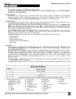
*These formats do not use
programmable codes,
but Event ID Codes to
identify the type of zone
as follows:
01 – Fire
02 – Panic
03 – Burglary
04 – Holdup
05 – Fire Supervision
06 – Fire Waterflow
08 – Heat Alarm
09 – General Alarm
0A – Auxiliary Alarm
(keypad displays "0")
0B – 24-Hour Auxiliary
Alarm
0C – Burg Perimeter
0D – Burg Interior
0E – Burg Exit/Entry
0F – Tamper
11 – AC Fail
12 – Low Battery (battery
test failure)
13 – Fire Tamper EZM
14 – Ground Fault
15 – Smoke
16 – Combustion
17 – Pull Station
18 – Duct
19 – Carbon Monoxide
RECEIVER FORMATS
ENTRY
RECEIVER FORMAT
0
Ademco Point ID*
1
SIA*
2
AES (not used)
3
GEMC-NL-MOD (Sends proprietary format to NAPCO NetLink NL-CSRCV Central Station Receiver)

