6
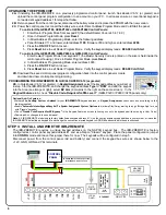
UPGRADING THE EPROM CHIP
2A.
If installing the IBR-ZREMOTE on a previously programmed control panel, launch Quickloader V6.12 (or greater) and
upload the control panel program configuration to an account on your PC. In all cases ensure a conventional keypad is
connected at keypad address 1 for steps that follow.
2B.
Remove power from the control panel, disconnect the battery wires and replace the EPROM with the new version.
2C.
Power the control panel, reconnect the battery wires, enter Direct Address Program Mode and Cold Start the panel:
To cold start the GEM-P186, GEM-P1632 or GEM-P1664 Control Panels:
1. Enter Dealer Program Mode from keypad #1 (the default Dealer Code is 4 5 6 7 8 9).
2. Once in Dealer Program Mode, press
Reset
.
3. In Direct Address Programming Mode, enter the following address:
Panel firmware V11 and lower, enter address
1198
; firmware V30 and higher, enter address
2286
4. Press the
ON / OFF
button to save.
5. Press
Reset
twice to exit Dealer Program Mode. Verify the keypad display reads:
E09-00 Cold Start
.
To cold start the GEM-P3200, GEM-P9600 or GEM-X255 Control Panels:
1. Enter Dealer Program Mode from keypad #1 (the Master Security Code is printed on the silver shield inside the
control panel housing). Once in Dealer Program Mode, press
Reset
.
2. In Direct Address Programming Mode, enter address 4093.
3. Press the
ON / OFF
button to save.
4. Press
Reset
twice to exit Dealer Program Mode. Verify the keypad display reads:
E09-00 Cold Start
.
2D.
Download the saved control panel program configuration back into the control panel or create
and download new control panel programming.
PROGRAMMING THE IBR-ZREMOTE IN QUICKLOADER V6.12 (or greater)
2E.
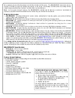
In Quickloader V6.12 (or greater), in
Keypad Assignment
, select the keypad address you will set up
in step 5 for the IBR-ZREMOTE, and change the keypad address
Type
to "
RCM
" and add the keypad
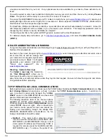
into the Area (see image at right), select
EZ Arm
(6 columns to the right on the same screen). In the
Keypad Features
tab, check "
Disable Code-Required-for-FM-Level 1
" (GEM-P3200 / P9600 / X255 panels only).
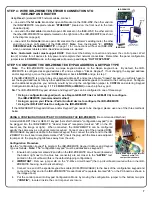
STEP 3: INSTALL AND WIRE THE IBR-ZREMOTE
The IBR-ZREMOTE requires a unique keypad address on the NAPCO keypad bus. The IBR-ZREMOTE is factory
configured as control panel keypad address #1 and as a Napco "Classic" keypad. Place the panel configuration jumper
into
CONFIG
mode and leave this jumper there for now. The keypads will be configured in step 5.
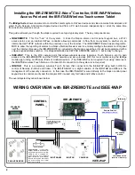
Disconnect power from the control panel (AC and battery) and connect the keypad bus wires as shown below to the
+12V, GND, GRN and YEL terminals.
Optional Add-On Features:
Activate
Fire, Auxiliary, Panic
and
Ambush
for your
IBR-ZREMOTE
keypad address (in
Keypad Assignment
, check each box according to the
features required)
Enable
"Automatic Interior Bypass/Easy Exit"
in
System Assignment
,
System Options
tab (allows Stay/Away arming through iBridge App for use
with "Classic" keypads)
Check
"Disable Code Required for EZ-Bypass"
in the Keypad Features screen (allowing zones to be bypassed without using a User Code)
Download ALL changes to the control panel
Note:
All IBR-ZREMOTE modules are factory defaulted as keypad address #1. Use the next available keypad address in your system, or leave the
IBR-ZREMOTE defaulted as keypad #1 and change the conventional wired keypad to ADDR #2 as described in these instructions.
RJ45
CABLE
M
A
C A
ddr
ess
(Exam
ple
:
00
-20
-4
A
-80
-81
-8B)
1
2
3
4
5
6
7
8
9
10
1
2
GRN
YEL
HEADER
SOCKET
J3
TO PANEL SERIAL PORT (only needed
for NL-MOD CS communication)
RED
BLK
RJ45
CABL
E
G
ND
DATA
BEL
L
IN0
IN1
IN2
IN
3
SUPV.
R.B.
+12V
LOCAL
DNLD
RJ12
CABLE
ETHERNET
ET
HERNE
T
3 WIRE
4 WIRE
CONTROL
PANEL
Summary of Contents for iBridge Suite
Page 18: ...18 NOTES...


