Napco iSecure Security System
All technical manuals are available in PDF format at
tech.napcosecurity.com
39
P R O G R A M M I N G
After the
ISEC
-
WIFI
module is installed, program the Go
-
Anywhere Hub using the iSecure Cloud Web Portal:
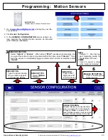
1.
Log into the iSecure Cloud Web Portal at
www.iSecureByNapco.com
as a Dealer (click
Dealer
Login
).
2.
Enter the
Radio Serial Number
and click
Submit
.
3.
Before Wi
-
Fi networks can be searched, click
Central
Station Reporting
and perform the following:
•
At the top of the screen, click to select the
Central Sta-
tion Reporting
radio button.
•
In the
COMMUNICATION TECHNOLOGY
pull
-
down,
select
IP with Cell Radio Backup
or
IP Only
, depend-
ing on your installation.
•
Check
Enable IP Supervision
, if desired.
•
In
Configuration Type
, select
Ethernet Preferred
with WiFi Backup (non
-
UL)
.
•
In
IP Configuration Type
, select
DHCP
.
•
Click
Save
to download your changes and restart the
system.
•
In
Dealer Entered Programming
, click
Search WiFi
Networks
(a popup will appear warning that scanning
may take up to 3 minutes). Click
Yes
to continue.
•
In the
Wi
-
Fi Networks
pull
-
down, find and select the
SSID name of the customer's network. Upon selection,
the
Security Type
and
Selected Network
fields will
automatically populate.
•
Type the
Password
of the customer's Wi
-
Fi network
and click
Save
.
Note:
The
Wi
-
Fi Module Version
will
not appear until connected.
E L E C T R I C A L R A T I N G S
Primary Operating Supply:
3.3VDC from Go
-
Anywhere
Smart Hub motherboard. 46mA standby current draw.
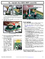
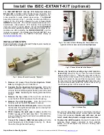
In addition, keep the wire away from the "Top Antenna"
that runs along the top edge of the motherboard, as
shown in Fig. 2.
9.
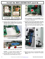
Insert the plastic
Standoff
into the bottom of the
ISEC
-
WIFI
(see Fig. 5).
10.
Use Fig. 6 to locate the two
Header Sockets
located
near the top left side of the Hub PCB (circled). Also lo-
cate the
Standoff hole
(arrow).
11.
With the small Antenna
Wire Plug located at the
top of the
ISEC
-
WIFI
PC
board,
carefully
align the Standoff with
its hole, and align the
two
Header Plugs
with
their
Header Sockets
(Fig. 6 & 7). Firmly
press the
ISEC
-
WIFI
into the PC board.
12.
Re
-
assemble the Go
-
Anywhere Smart Hub
enclosure as directed in
"
Install
the
Go
-
Anywhere Hub
" on
page 10.
14. Install the ISEC
-
WIFI (cont'd)
Fig. 5: Standoff (arrow)
Fig. 7: Align and insert ISEC
-
WIFI (PC Board)
Fig. 4: Antenna Wire Plug and Socket
Plug
Socket
Fig. 6: "Header Sockets" (circled)

