64
All technical manuals are available in PDF format at
tech.napcosecurity.com
Napco iSecure Security System
function reflect the latest sample readings that were automatically
retrieved by the keypad every 15 minutes.
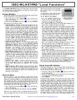
The first to be displayed is the keypad RF ID number:
•
rF id
-
The numbers displayed are identical to the RF ID num-
bers on the labels that are affixed to the PC board and to the
rear keypad case. The RF ID number is needed to learn the
keypad into the system. There are 7 hexadecimal numbers
that appear following the "
rF Id
" (each pair appears for two
seconds). Last single digit or letter is check digit.
Example:
"
rF
,
Id
,
b2
,
3d
,
5F
,
A
"
The remaining signal strength readings always follow two letters,
as follows:
•
FL
-
The numbers that follow correspond to the weakest RF
signal received by the (LCD) keypad from any device in the
system (
FL
= "Floor Level").
•
LL
-
Same as the "
LL
" description in the previous function,
"
Walk Test Mode
", described earlier in this section.
•
OL
-
In one of several efforts to save keypad battery power, the
sensitivity level of the keypad is adjusted as needed, depend-
ing upon calculations based upon the "
LL
" signal (above), and
is displayed here for reference. Depending on the "
LL
" signal
level, if the keypad is adjudged to be in "close" proximity to its
connected Hub and also to another, separate iSecure system,
the keypad sensitivity threshold is adjusted to save battery
power, and to also prevent the other, separate iSecure system
from needlessly waking up the keypad when in an idle state.
•
HL
-
Same as the "
HL
" description in the previous function,
"
Walk Test Mode
", described earlier in this section.
•
LP
-
Similar to "
OL
", above, this reading exists as a result of
another effort to save keypad battery power. The transmission
level of the keypad is adjusted as needed, depending upon
calculations based upon the "
HL
" signal (above), and is dis-
played here for reference.
•
Operating Frequency
-
Displays the radio operating frequen-
cy of the iSecure system, in MHz. For example, a frequency
of 928.75MHz is displayed as "
Fr
,
92
,
87
,
50
".
Reset Microcontroller
Performing this feature is equivalent to removing the keypad bat-
tery power and then restoring battery power. All keypad settings
are retained.
1.
Press and hold the keypad
AREA
(
) button until "
LF
" ap-
pears in the Window.
2.
Press
RESET
, then press
ENTER
.
Keypad Window Backlight
The keypad face contains a Room Light Sensor that automatically
measures the ambient light level to determine if the keypad Win-
dow backlight needs to be turned on for a few seconds after a
keypad button press. A lit backlight ensures the Window contents
are displayed clearly in a dark room. In a bright room, the back-
light is not needed and thus remains off to save battery power.
This Room Light Sensor threshold can be adjusted as well as
enabled/disabled, as described in the
Operating Guide for the
ISEC
-
WL
-
KEYPAD Wireless Battery
-
Powered Keypad
(OI400), in
the section "
KEYPAD WINDOW BACKLIGHT
".
ISEC
-
WL
-
KEYPAD "Local Functions" (cont'd)
RF Channel Scan
If the system is experiencing 900Mhz communication issues and
there is the belief that a nearby iSecure system might be interfering
with the system to be installed, the ISEC
-
WL
-
KEYPAD can be used
as a "scanner" to scan for the presence of other nearby iSecure
radio signals and determine if the nearby system is using the same
900Mhz RF Channel as the system you are installing. The factory
-
assigned
Channel
number is located on a label affixed to the OI404
card included along with your iSecure printed manuals (see page 7
for details about this OI404 card and to find the factory
-
assigned
"
CH#
").
Do not perform this procedure in normal installations
.
1.
With the Go
-
Anywhere Hub up and running, "unlearn" (remove)
the ISEC
-
WL
-
KEYPAD from the system by deleting the keypad
from the
KEYPADS
screen in the iSecure Cloud Web Portal (at
www.iSecureByNapco.com
) and uploading this revised data (of
the deleted keypad) to the Hub. Optionally, you can perform the
ISEC
-
WL
-
KEYPAD "Factory Reset" process on page 61.
2.
Power off your iSecure Hub by unplugging AC and opening the
Hub enclosure to disconnect the battery. Removing power en-
sures the Hub to be installed will not be detected by the scan.
3.
At the ISEC
-
WL
-
KEYPAD, press and hold the
AREA
(
) but-
ton until "
LF
" appears in the keypad display, then release.
4.
Refer to the OI404 card and the "
CH#
" that appears on the
900MHz transceiver label. Press
1
and then change the channel
number by using the
AWAY
(channel up) or
STAY
(channel
down) buttons. To select the channel, press
ENTER
.
5.
For the selected Channel, if no signal is received from a separate
nearby iSecure system, the keypad will display "
cS
" and then
"
00
". However, if any signal is received from a separate nearby
iSecure system, the keypad will display "
cS
" and then an RSSI
(
Received Signal Strength Indicator
) value in negative dBm units.
Note:
In this system, the values range from "
40
" to "
105
", where
"
105
" (i.e. "
-
105dBm") is the lower/weaker signal strength.
The keypad will then display the same received signal strength
value but converted to a zero through 10 scale (with "
00
" the
minimum and "
10
" the maximum signal strength).
Best Scan Result:
A displayed value of zero ("
00
") indicates
the lack of any other iSecure system(s) that are using the same
900Mhz RF channel as the system you are installing.
If the scan reveals interference and you wish to assign a new
Channel number, use your Dealer Login to access the iSecure
Cloud Web Portal (at
www.iSecureByNapco.com
),
GENERAL
SETTINGS
screen,
RF Channel Number
pull
-
down field.
Note:
Be aware that two systems with different Channel num-
bers may share the same iSecure frequency and may interfere.
Factory default systems are programmed with 32 Channel num-
bers and five (5) iSecure frequencies, as follows:
•
Channel 1
-
6 = frequency 1
•
Channel 7
-
12 = frequency 2
•
Channel 13
-
20 = frequency 3
•
Channel 21
-
26 = frequency 4
•
Channel 27
-
32 = frequency 5
If interference is detected by the scan, use the iSecure Cloud Web
Portal to assign a new Channel. Be aware that the Web Portal
provides expanded control, allowing you to assign one of up to
32
frequencies, with each Channel number (1
-
32) directly corre-
sponding to its numbered frequency (1
-
32).
Note:
All 900MHz
devices must remain un
-
learned when a new Channel is as-
signed.
Re
-
scan the system to confirm there are no additional nearby iSe-
cure radio signals that are using the same 900Mhz RF Channel as
the system you are installing.

