EN
W415-1467 / 04.22.15
9
3.0 PRE-INSTALLATION PREPARATION
Have an authorized dealer install the appliance. If you install the appliance yourself, have your dealer review
your installation plans and/or installation.
Draw out a detailed plan of the installation including dimensions and verify the dimensions with the require-
ments listed in this manual.
You may wish to adjust the appliance position slightly to ensure the vent does not intersect with a framing
member. Appliance must be positioned so that no combustibles are within, or can swing within (e.g. drapes,
doors), 48” (1219.2mm) of the front of the appliance.
67.1B
3.1 APPLIANCE
PLACEMENT
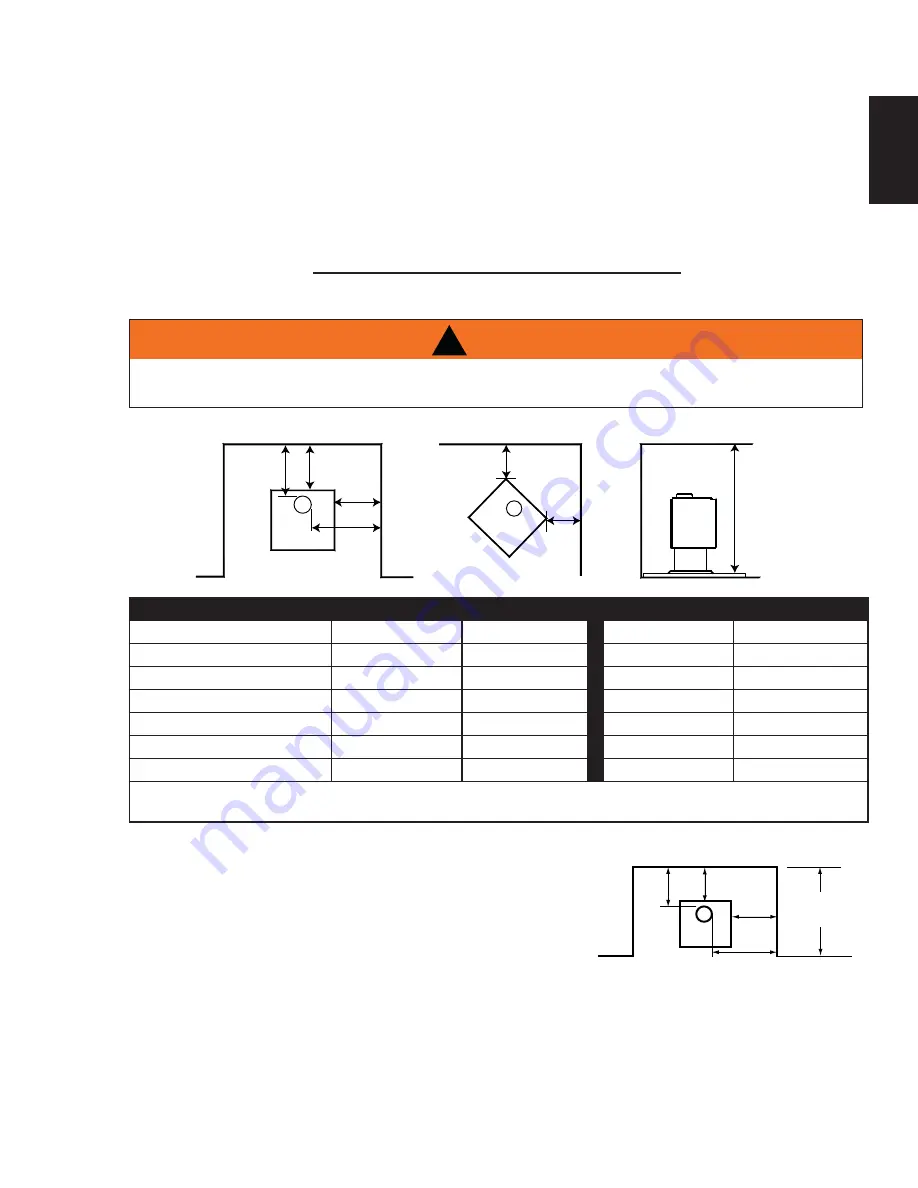
3.2 CLEARANCE TO COMBUSTIBLES
DO NOT INSTALL INTO ANY AREA HAVING A HEIGHT LESS THAN 7 FEET (2.1m)
(CEILING OF ENCLOSURE TO APPLIANCE BOTTOM, EXCLUDING HEARTH HEIGHT).
!
WARNING
BACK WALL
B
SIDE WALL
A
BACK WALL
C
SIDE WALL
F
D
E
E
PARALLEL & CORNER
SINGLE WALL CONNECTOR
DOUBLE WALL CONNECTOR
1100ML / 1100C
1400ML / 1400C
1100ML / 1100C
1400ML / 1400C
SIDEWALL (A)
12" (305mm)
12" (305mm)
10" (254mm)
10" (254mm)
SIDEWALL TO FLUE (B)
21 3/4" (552mm)
21 3/4" (552mm)
19 3/4" (502mm)
19 3/4" (502mm)
BACKWALL (C)
10" (254mm)
12" (305mm)
6"(152mm)
6" (152mm)
BACKWALL TO FLUE (D)
13 1/2" (343mm)
16 1/2" (419mm)
9 1/2" (241mm)
10 1/2" (267mm)
CORNER (E)
6" (152mm)
6" (152mm)
2" (51mm)
4" (102mm)
CEILING (F)
84" (2134mm)
84" (2134mm)
84" (2134mm)
84" (2134mm)
Clearances can be reduced with shielding acceptable to local authorities. Reduced installation must comply
with NFPA 211 or CAN/CSA-B365.
14"
23"
ALCOVE
4 FOOT
MAX
9”
6”
1100 series only may be installed, using a listed double wall connector,
such as Security DL6 in Canada, the Simpson Duravent Plus DVL in
the USA or an equivalent double wall connector, into an alcove having
a depth of no more than 4 feet and a height of at least 7 feet.
The minimum clearances are as shown.
3.3 ALCOVE
INSTALLATION


