W415-2159 / D / 11.24.17
37
IOM
12.3 GAS INLET PRESSURE
12.4 LEAK TESTING
12.5 PURGING GAS LINES
H17.2B
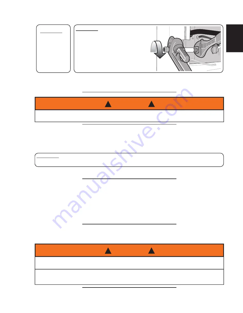
IMPORTANT:
ALWAYS USE A BACKUP
WRENCH TO PREVENT TWISTING
OF THE GAS VALVE. ANY
STRAINS ON THE GAS VALVE
CAN AFFECT POSITIONING OF
THE ORIFICES RELATIVE TO THE
BURNERS. THIS COULD RESULT
IN FAULTY BURNER OPERATION.
Install a manual gas shut-off valve and dirt pocket as close to the furnace as possible. Some local codes call
for the manual gas shut-off valve to be located between 4 feet (1.2m) to 5 feet (1.5m) above
fl
oor level to
prevent tampering by small children. Ensure that the valve is readily accessible.
IMPORTANT:
ENSURE
THAT THE
GAS VALVE
IS NOT
SUBJECTED
TO HIGH
PRESSURES.
H3.19
DISCONNECT THE MANUAL SHUT-OFF VALVE AND GAS VALVE DURING ANY
PRESSURE TESTING THAT EXCEEDS 1/2 P.S.I.G. (3.45 KPA).
WARNING
!
!
H17.3.3A
The natural gas inlet supply pressure should be 5” to 7” w.c. (7” w.c. recommended). These pressures must be
maintained while all other gas
fi
red appliances are operating at maximum conditions.
IMPORTANT:
DO NOT EXCEED 13” W.C. INLET PRESSURE.
The gas valve has two adjustable internal regulator for controlling burner manifold pressure. Burner manifold
high
fi
re and low
fi
re pressures are listed on the furnace rating plate.
H17.4
All new gas piping installations should be pressure tested as speci
fi
ed by CAN/CSA-B149.1 & 2, or NFPA 54
ANSI Z223.1 or ANSI/NFPA 58,
“Standard for the Storage and Handling of Liquefi ed Petroleum Gases.”
Gas piping that has not been pressure tested, from the manual shut-off valve to the furnace gas valve for
example, should be leak tested using an electronic combustible gas detector, a commercially prepared leak
detector, or other locally approved method.
H3.20
NEVER USE A MATCH, TAPER, CIGARETTE LIGHTER, FLAME OR ANY OTHER IGNITION
SOURCE TO CHECK FOR LEAKS IN A GAS LINE.
FAILURE TO ADHERE TO THIS WARNING CAN CAUSE A FIRE OR EXPLOSION
RESULTING IN PROPERTY DAMAGE, PERSONAL INJURY, OR LOSS OF LIFE.
WARNING
!
!
Summary of Contents for 9600E E-STAR Series
Page 27: ...W415 2159 D 11 24 17 27 IOM FIGURE 14A DIRECT VENT TERMINAL CLEARANCES...
Page 28: ...W415 2159 D 11 24 17 28 IOM IOM FIGURE 14B NON DIRECT VENT TERMINAL CLEARANCES...
Page 57: ...W415 2159 D 11 24 17 57 IOM 23 0 SERVICE HISTORY 43 1...
Page 58: ...W415 2159 D 11 24 17 58 IOM IOM 24 0 NOTES 44 1...
Page 74: ...6 0 NOTES 44 1 W415 2159 D 11 24 17 UM 74...


