W415-0616 / E / 10.08.08
45
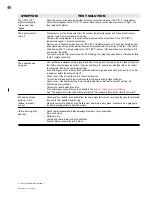
SYMPTOM
TEST SOLUTION
The auger motor is
not functioning
normally
Feed rate dial has
no effect on the fire
(timer control only)
The convection
blower is not
functioning
normally
The heater will not
operate when hot
- Hopper lid must be closed.
- Make certain the exhaust blower is operating.
- Check the condition of the vacuum hose (located on the left side of the heater). Should not be cracked
or torn.
- Check the manual reset button on the 200°F (93°C) temperature sensor. Before re-setting the red
button, check for the cause of the over-heating.
- Check that the auger set screw is tight and not slipping.- If the auger still does not work, then apply
115V AC directly to the auger motor. If it still does not work, replace it.
- Check the auger by bypassing the 200°F (93°) temperature sensor with a jumper wire. If auger works,
replace the sensor.
-
The auger shaft may be jammed. For more information see “IN THE EVENT OF A JAMMED AUGER”
section.
- Check the vacuum sensor by placing a jumper wire between the blue wire and the black wire that are
attached to the sensor. If the auger works, test to see if the exhaust blower is producing enough
vacuum (may require cleaning).
- If not, replace the vacuum sensor.
- Secure all connections to the power control module.
- Perform a resistance test to the potentiometer by placing the two test leads from a multi meter into the
leads of the potentiometer. The potentiometer should have a range of 850 KΩ (± 10%).
Potentiometer readings:
Full counter-clockwise (switched off) = open circuit, overload or infinite resistance
Low fire .......... 900 KΩ to 1,050 KΩ
High fire ......... 56 KΩ to 62 KΩ
If the range is not close or does not vary then replace the potentiometer.
- Using the wiring diagram, compare all the connections between the controller, switch, and the
convection blower.
- If the convection motor will not run, apply 115V AC to the motor directly. Replace the blower controller if
the motor runs. The convection blower has failed if the motor does not run. Replace the blower.
- If the convection blower runs on high at all times (no control with the blower controller), check the
connections from the 160°F (71°C) sensor (located on the upper left side on the rear of the fire wall) and
convection blower controller to the blower. Disconnect one of the wires from the sensor and if control of
the convection blower returns to the blower controller, replace the sensor.
- If the motor is still on high, re-connect the sensor and replace the convection blower controller.
General
- Check the hopper for fuel.
- Incorrect air damper setting may cause excessive air to consume the fire too quickly before the next
drop of fuel. Therefore leaving the fuel completely unburned in the burn pot and will cause the fuel to
burn cold and very slowly. Fuel also may build up and smother the fire.
NOTE: The unit may require a change to the vent system or installation of fresh air to correct air to
fuel ratio problems.
- Combustion blower failure may occur because it is not turning fast enough to generate the proper
vacuum in the fire box. Do a visual check to see if the motor is turning.
- Check vacuum levels in the exhaust channel by bypassing the vacuum switch, then remove the vacuum
hose from vacuum switch. When checking the vacuum exhaust place the open end of the vacuum hose
on the gauge (readings must be above 0.10" W.C. on low fire).
NOTE: if the motor fails to reach a 0.10" W.C., then replace the combustion blower.
- Poor quality fuel may not produce enough heat to keep the stove burning or operational.
- If the exhaust temperature sensor fails try bypassing the sensor located on the exhaust blower. If the
stove operates properly, the unit may require cleaning or a new sensor. Contact your local deal for
service.
- Unplug the stove, open the left side panel and jump the two brown leads that are attached to the 140°F
(60°C) temperature sensor. If the stove operates replace the 140°F (60°C) sensor.
TP - PEllET TROUblE ShOOTING 2
Summary of Contents for Auburn NPS40
Page 1: ...W415 0616 E 10 08 08 1 W415 0616 E 10 08 08 10 00 ...
Page 35: ...W415 0616 E 10 08 08 35 10 0 Normal operating sounds TP OPERATING SOUNDS_PELLET Figure 10 0 ...
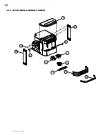
Page 40: ...W415 0616 E 10 08 08 40 12 1 Common replacement parts ...
Page 42: ...W415 0616 E 10 08 08 42 69 28 38 70 41 40 53 54 75 71 69 72 12 3 Npi40 replacement parts ...
Page 48: ...W415 0616 E 10 08 08 48 NOTES 15 0 notes TP NOTES ...


