


7.3 temperature display
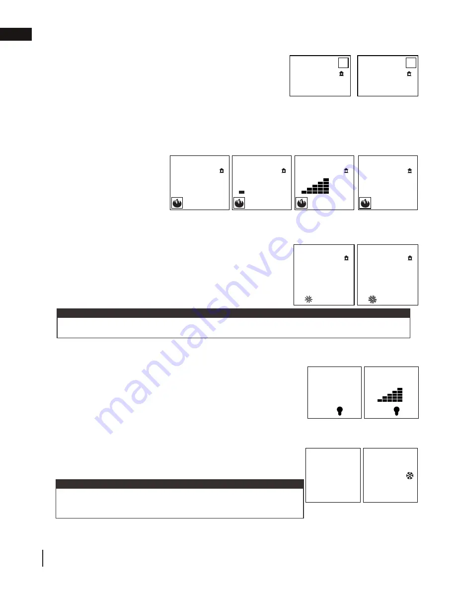
7.4 flame height
7.5 blower speed
7.7 continuous pilot / intermittent pilot (CPI / IPI) selection
23.2
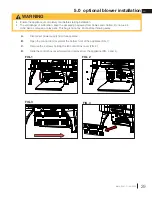
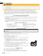
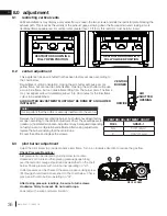
A. Press the ON/OFF key on the transmitter. The transmitter display will show
all active icons on the screen. A single “beep” from the receiver will confirm
reception of the command.
Blue LCD Display
On / Off Key
Up / Down Arrow Key
Mode Key
Temperature Key
73
23
76
°F
68
Room Temperature
Set Temperature
76
°F
MAX
76
°F
OFF
76
°F
76
°F
76
°F
Hi
Flame Off
Flame at level 1
Flame at level 5
Flame at “Hi” level 6
76
°F
child lock
76
°F
OFF
76
°F
ON
76
°F
76
°F
68
76
°F
Hi
76
°F
OFF
76
°F
76
°F
IPI
76
°F
CPI
ON
SMART
°F
°C
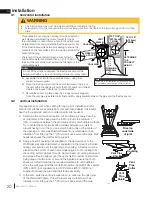
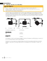
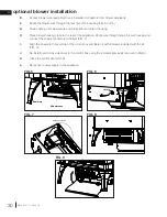
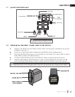
ADD TITLE: TEMPERATURE DISPLAY
A. With the system in the
off
position, press the Temperature Key and the
mode key
at the same time to change from degrees F to C.
B. Look at the LCD screen on the transmitter to verify that a C or F is
visible to the right of the Room Temperature display.
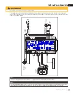
ADD TITLE: HAND HELD REMOTE OPERATION
The remote transmitter can operate as a room thermostat.
The thermostat can be set to a desired temperature to control the comfort level in the
room.
A. Press the
thermostat
key. The LCD display on the transmitter will show that the
room is
on
and the set temperature is now displayed.
B. To adjust the set temperature, press the
mode key
until the desired set
temperature is displayed on the LCD screen of the transmitter.
Blue LCD Display
On / Off Key
Up / Down Arrow Key
Mode Key
Temperature Key
73
23
76
°F
68
Room Temperature
Set Temperature
76
°F
MAX
76
°F
OFF
76
°F
76
°F
76
°F
Hi
Flame Off
Flame at level 1
Flame at level 5
Flame at “Hi” level 6
76
°F
child lock
76
°F
OFF
76
°F
ON
76
°F
76
°F
68
76
°F
Hi
76
°F
OFF
76
°F
76
°F
IPI
76
°F
CPI
ON
SMART
°F
°C
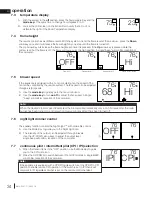
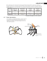
ADD TITLE: ROOM THERMOSTAT
ADD TITLE: SMART THERMOSTAT
The Smart Thermostat function adjusts the flame height according to the difference between
the set temperature and the actual room temperature. As the room temperature gets closer to
the set point the Smart Function will automatically adjust the flame down.
A. Press the thermostat key until the word
SMART
appears to the right of the temperature
bulb graphic.
B. To adjust the set temperature, press the
mode key
until the desired set temperature is
displayed on the LCD screen at the transmitter.
Blue LCD Display
On / Off Key
Up / Down Arrow Key
Mode Key
Temperature Key
73
23
76
°F
68
Room Temperature
Set Temperature
76
°F
MAX
76
°F
OFF
76
°F
76
°F
76
°F
Hi
Flame Off
Flame at level 1
Flame at level 5
Flame at “Hi” level 6
76
°F
child lock
76
°F
OFF
76
°F
ON
76
°F
76
°F
68
76
°F
Hi
76
°F
OFF
76
°F
76
°F
IPI
76
°F
CPI
ON
SMART
°F
°C
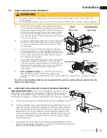
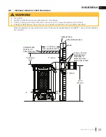
The remote control has six (6) flame levels. With the system on and the flame level at the maximum, press the
Down
arrow key once and it will reduce the flame height by one step until the flame is turned off.
The Up Arrow Key will increase the flame height each time it is pressed. If the
Up
arrow key is pressed while the
system is on but the flame is off, the flame will come on at the high position. A single “beep” will confirm reception of
the command.
ADD TITLE: FLAME HEIGHT
Blue LCD Display
On / Off Key
Up / Down Arrow Key
Mode Key
Temperature Key
73
23
76
°F
68
Room Temperature
Set Temperature
76
°F
MAX
76
°F
OFF
76
°F
76
°F
76
°F
Hi
Flame Off
Flame at level 1
Flame at level 5
Flame at “Hi” level 6
76
°F
child lock
76
°F
OFF
76
°F
ON
76
°F
76
°F
68
76
°F
Hi
76
°F
OFF
76
°F
76
°F
IPI
76
°F
CPI
ON
SMART
°F
°C
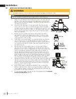
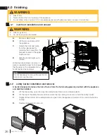
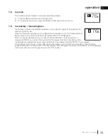
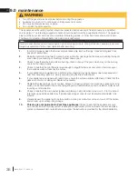
If the appliance is equipped with a hot air circulating fan, the speed of the
fan can be controlled by the remote system. The fan speed can be adjusted
through six (6) speeds.
A. Use the
mode key
to guide you to the fan control icon.
B. Use the
mode key
to turn
on
/
off
or adjust the fan speed. A single
“beep” will confirm reception of the command.
ADD TITLE: FAN SPEED
Blue LCD Display
On / Off Key
Up / Down Arrow Key
Mode Key
Temperature Key
73
23
76
°F
68
Room Temperature
Set Temperature
76
°F
MAX
76
°F
OFF
76
°F
76
°F
76
°F
Hi
Flame Off
Flame at level 1
Flame at level 5
Flame at “Hi” level 6
76
°F
child lock
76
°F
OFF
76
°F
ON
76
°F
76
°F
68
76
°F
Hi
76
°F
OFF
76
°F
76
°F
IPI
76
°F
CPI
ON
SMART
°F
°C
When the desired blower speed is selected, the blower will automatically come on 5 minutes after the main
burner has been turned on and remain on twelve minutes after it has been turned off.
note:
23.2
A. Press the ON/OFF key on the transmitter. The transmitter display will show
all active icons on the screen. A single “beep” from the receiver will confirm
reception of the command.
Blue LCD Display
On / Off Key
Up / Down Arrow Key
Mode Key
Temperature Key
73
23
76
°F
68
Room Temperature
Set Temperature
76
°F
MAX
76
°F
OFF
76
°F
76
°F
76
°F
Hi
Flame Off
Flame at level 1
Flame at level 5
Flame at “Hi” level 6
76
°F
child lock
76
°F
OFF
76
°F
ON
76
°F
76
°F
68
76
°F
Hi
76
°F
OFF
76
°F
76
°F
IPI
76
°F
CPI
ON
SMART
°F
°C
ADD TITLE: TEMPERATURE DISPLAY
A. With the system in the
off
position, press the Temperature Key and the
mode key
at the same time to change from degrees F to C.
B. Look at the LCD screen on the transmitter to verify that a C or F is
visible to the right of the Room Temperature display.
ADD TITLE: HAND HELD REMOTE OPERATION
The remote transmitter can operate as a room thermostat.
The thermostat can be set to a desired temperature to control the comfort level in the
room.
A. Press the
thermostat
key. The LCD display on the transmitter will show that the
room is
on
and the set temperature is now displayed.
B. To adjust the set temperature, press the
mode key
until the desired set
temperature is displayed on the LCD screen of the transmitter.
Blue LCD Display
On / Off Key
Up / Down Arrow Key
Mode Key
Temperature Key
73
23
76
°F
68
Room Temperature
Set Temperature
76
°F
MAX
76
°F
OFF
76
°F
76
°F
76
°F
Hi
Flame Off
Flame at level 1
Flame at level 5
Flame at “Hi” level 6
76
°F
child lock
76
°F
OFF
76
°F
ON
76
°F
76
°F
68
76
°F
Hi
76
°F
OFF
76
°F
76
°F
IPI
76
°F
CPI
ON
SMART
°F
°C
ADD TITLE: ROOM THERMOSTAT
ADD TITLE: SMART THERMOSTAT
The Smart Thermostat function adjusts the flame height according to the difference between
the set temperature and the actual room temperature. As the room temperature gets closer to
the set point the Smart Function will automatically adjust the flame down.
A. Press the thermostat key until the word
SMART
appears to the right of the temperature
bulb graphic.
B. To adjust the set temperature, press the
mode key
until the desired set temperature is
displayed on the LCD screen at the transmitter.
Blue LCD Display
On / Off Key
Up / Down Arrow Key
Mode Key
Temperature Key
73
23
76
°F
68
Room Temperature
Set Temperature
76
°F
MAX
76
°F
OFF
76
°F
76
°F
76
°F
Hi
Flame Off
Flame at level 1
Flame at level 5
Flame at “Hi” level 6
76
°F
child lock
76
°F
OFF
76
°F
ON
76
°F
76
°F
68
76
°F
Hi
76
°F
OFF
76
°F
76
°F
IPI
76
°F
CPI
ON
SMART
°F
°C
The remote control has six (6) fl ame levels. With the system on and the fl ame level at the maximum, press the
Down
arrow key once and it will reduce the fl ame height by one step until the fl ame is turned off.
The Up Arrow Key will increase the fl ame height each time it is pressed. If the
Up
arrow key is pressed while the
system is on but the fl ame is off, the fl ame will come on at the high position. A single “beep” will confi rm reception of
the command.
ADD TITLE: FLAME HEIGHT
Blue LCD Display
On / Off Key
Up / Down Arrow Key
Mode Key
Temperature Key
73
23
76
°F
68
Room Temperature
Set Temperature
76
°F
MAX
76
°F
OFF
76
°F
76
°F
76
°F
Hi
Flame Off
Flame at level 1
Flame at level 5
Flame at “Hi” level 6
76
°F
child lock
76
°F
OFF
76
°F
ON
76
°F
76
°F
68
76
°F
Hi
76
°F
OFF
76
°F
76
°F
IPI
76
°F
CPI
ON
SMART
°F
°C
If the appliance is equipped with a hot air circulating fan, the speed of the
fan can be controlled by the remote system. The fan speed can be adjusted
through six (6) speeds.
A. Use the
mode key
to guide you to the fan control icon.
B. Use the
mode key
to turn
on
/
off
or adjust the fan speed. A single
“beep” will confirm reception of the command.
ADD TITLE: FAN SPEED
Blue LCD Display
On / Off Key
Up / Down Arrow Key
Mode Key
Temperature Key
73
23
76
°F
68
Room Temperature
Set Temperature
76
°F
MAX
76
°F
OFF
76
°F
76
°F
76
°F
Hi
Flame Off
Flame at level 1
Flame at level 5
Flame at “Hi” level 6
76
°F
child lock
76
°F
OFF
76
°F
ON
76
°F
76
°F
68
76
°F
Hi
76
°F
OFF
76
°F
76
°F
IPI
76
°F
CPI
ON
SMART
°F
°C
Blue LCD Display
On / Off Key
Up / Down Arrow Key
Mode Key
Temperature Key
73
23
76
°F
68
Room Temperature
Set Temperature
76
°F
MAX
76
°F
OFF
76
°F
76
°F
76
°F
Hi
Flame Off
Flame at level 1
Flame at level 5
Flame at “Hi” level 6
76
°F
child lock
76
°F
OFF
76
°F
ON
76
°F
76
°F
68
76
°F
Hi
76
°F
OFF
76
°F
76
°F
IPI
76
°F
CPI
ON
SMART
°F
°C
Blue LCD Display
On / Off Key
Up / Down Arrow Key
Mode Key
Temperature Key
73
23
76
°F
68
Room Temperature
Set Temperature
76
°F
MAX
76
°F
OFF
76
°F
76
°F
76
°F
Hi
Flame Off
Flame at level 1
Flame at level 5
Flame at “Hi” level 6
76
°F
child lock
76
°F
OFF
76
°F
ON
76
°F
76
°F
68
76
°F
Hi
76
°F
OFF
76
°F
76
°F
IPI
76
°F
CPI
ON
SMART
°F
°C
When the desired blower speed is selected, the blower will automatically come on 5 minutes after the main
burner has been turned on and remain on twelve minutes after it has been turned off.
note:
23.2
A. Press the ON/OFF key on the transmitter. The transmitter display will show
all active icons on the screen. A single “beep” from the receiver will confirm
reception of the command.
Blue LCD Display
On / Off Key
Up / Down Arrow Key
Mode Key
Temperature Key
73
23
76
°F
68
Room Temperature
Set Temperature
76
°F
MAX
76
°F
OFF
76
°F
76
°F
76
°F
Hi
Flame Off
Flame at level 1
Flame at level 5
Flame at “Hi” level 6
76
°F
child lock
76
°F
OFF
76
°F
ON
76
°F
76
°F
68
76
°F
Hi
76
°F
OFF
76
°F
76
°F
IPI
76
°F
CPI
ON
SMART
°F
°C
ADD TITLE: TEMPERATURE DISPLAY
A. With the system in the
off
position, press the Temperature Key and the
mode key
at the same time to change from degrees F to C.
B. Look at the LCD screen on the transmitter to verify that a C or F is
visible to the right of the Room Temperature display.
ADD TITLE: HAND HELD REMOTE OPERATION
The remote transmitter can operate as a room thermostat.
The thermostat can be set to a desired temperature to control the comfort level in the
room.
A. Press the
thermostat
key. The LCD display on the transmitter will show that the
room is
on
and the set temperature is now displayed.
B. To adjust the set temperature, press the
mode key
until the desired set
temperature is displayed on the LCD screen of the transmitter.
Blue LCD Display
On / Off Key
Up / Down Arrow Key
Mode Key
Temperature Key
73
23
76
°F
68
Room Temperature
Set Temperature
76
°F
MAX
76
°F
OFF
76
°F
76
°F
76
°F
Hi
Flame Off
Flame at level 1
Flame at level 5
Flame at “Hi” level 6
76
°F
child lock
76
°F
OFF
76
°F
ON
76
°F
76
°F
68
76
°F
Hi
76
°F
OFF
76
°F
76
°F
IPI
76
°F
CPI
ON
SMART
°F
°C
ADD TITLE: ROOM THERMOSTAT
ADD TITLE: SMART THERMOSTAT
The Smart Thermostat function adjusts the flame height according to the difference between
the set temperature and the actual room temperature. As the room temperature gets closer to
the set point the Smart Function will automatically adjust the flame down.
A. Press the thermostat key until the word
SMART
appears to the right of the temperature
bulb graphic.
B. To adjust the set temperature, press the
mode key
until the desired set temperature is
displayed on the LCD screen at the transmitter.
Blue LCD Display
On / Off Key
Up / Down Arrow Key
Mode Key
Temperature Key
73
23
76
°F
68
Room Temperature
Set Temperature
76
°F
MAX
76
°F
OFF
76
°F
76
°F
76
°F
Hi
Flame Off
Flame at level 1
Flame at level 5
Flame at “Hi” level 6
76
°F
child lock
76
°F
OFF
76
°F
ON
76
°F
76
°F
68
76
°F
Hi
76
°F
OFF
76
°F
76
°F
IPI
76
°F
CPI
ON
SMART
°F
°C
The remote control has six (6) flame levels. With the system on and the flame level at the maximum, press the
Down
arrow key once and it will reduce the flame height by one step until the flame is turned off.
The Up Arrow Key will increase the flame height each time it is pressed. If the
Up
arrow key is pressed while the
system is on but the flame is off, the flame will come on at the high position. A single “beep” will confirm reception of
the command.
ADD TITLE: FLAME HEIGHT
Blue LCD Display
On / Off Key
Up / Down Arrow Key
Mode Key
Temperature Key
73
23
76
°F
68
Room Temperature
Set Temperature
76
°F
MAX
76
°F
OFF
76
°F
76
°F
76
°F
Hi
Flame Off
Flame at level 1
Flame at level 5
Flame at “Hi” level 6
76
°F
child lock
76
°F
OFF
76
°F
ON
76
°F
76
°F
68
76
°F
Hi
76
°F
OFF
76
°F
76
°F
IPI
76
°F
CPI
ON
SMART
°F
°C
If the appliance is equipped with a hot air circulating fan, the speed of the
fan can be controlled by the remote system. The fan speed can be adjusted
through six (6) speeds.
A. Use the
mode key
to guide you to the fan control icon.
B. Use the
mode key
to turn
on
/
off
or adjust the fan speed. A single
“beep” will confi rm reception of the command.
ADD TITLE: FAN SPEED
Blue LCD Display
On / Off Key
Up / Down Arrow Key
Mode Key
Temperature Key
73
23
76
°F
68
Room Temperature
Set Temperature
76
°F
MAX
76
°F
OFF
76
°F
76
°F
76
°F
Hi
Flame Off
Flame at level 1
Flame at level 5
Flame at “Hi” level 6
76
°F
child lock
76
°F
OFF
76
°F
ON
76
°F
76
°F
68
76
°F
Hi
76
°F
OFF
76
°F
76
°F
IPI
76
°F
CPI
ON
SMART
°F
°C
Blue LCD Display
On / Off Key
Up / Down Arrow Key
Mode Key
Temperature Key
73
23
76
°F
68
Room Temperature
Set Temperature
76
°F
MAX
76
°F
OFF
76
°F
76
°F
76
°F
Hi
Flame Off
Flame at level 1
Flame at level 5
Flame at “Hi” level 6
76
°F
child lock
76
°F
OFF
76
°F
ON
76
°F
76
°F
68
76
°F
Hi
76
°F
OFF
76
°F
76
°F
IPI
76
°F
CPI
ON
SMART
°F
°C
Blue LCD Display
On / Off Key
Up / Down Arrow Key
Mode Key
Temperature Key
73
23
76
°F
68
Room Temperature
Set Temperature
76
°F
MAX
76
°F
OFF
76
°F
76
°F
76
°F
Hi
Flame Off
Flame at level 1
Flame at level 5
Flame at “Hi” level 6
76
°F
child lock
76
°F
OFF
76
°F
ON
76
°F
76
°F
68
76
°F
Hi
76
°F
OFF
76
°F
76
°F
IPI
76
°F
CPI
ON
SMART
°F
°C
When the desired blower speed is selected, the blower will automatically come on 5 minutes after the main
burner has been turned on and remain on twelve minutes after it has been turned off.
note:
Your remote system may have a built in timer (in thermostat mode) that enables the blower (if equipped) to cycle
on and off automatically when the burner turns on and off. With the remote control fan speed preset at the
preferred speed, the blower will come on approximately 5 minutes after the main burner comes on and will shut off
approximately 12 minutes after the burner shuts off.
This time delay is designed to maximize the blower distribution of heated air.
If at any time the burner re-ignites before the twelve minutes are over, the fan will continue to run.
ADD TITLE: TIMED BLOWER
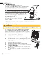
ADD TITLE: CHILD PROOF FUNCTION
This function will lock the keys to avoid unsupervised operation.
A. Press the MODE and UP keys at the same time.
B. To de-activate this function, press the MODE and UP keys at the same time.
ADD TITLE: NIGHT LIGHT
The auxiliary function controls the AUX power outlet on the Control Module
which controls the NIGHT LIGHT™.
A. Use the Mode Key to guide you to the AUX icon.
B. Pressing the Up Arrow Key will activate the NIGHT LIGHT™.
C. Pressing the Down Arrow Key will turn the NIGHT LIGHT™ off. A single
“beep” will confirm the reception of the command.
Blue LCD Display
On / Off Key
Up / Down Arrow Key
Mode Key
Temperature Key
73
23
76
°F
68
Room Temperature
Set Temperature
76
°F
MAX
76
°F
OFF
76
°F
76
°F
76
°F
Hi
Flame Off
Flame at level 1
Flame at level 5
Flame at “Hi” level 6
76
°F
child lock
76
°F
OFF
76
°F
ON
76
°F
76
°F
68
76
°F
Hi
76
°F
OFF
76
°F
76
°F
IPI
76
°F
CPI
ON
SMART
°F
°C
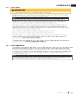
The life span of the remote batteries depends on various factors: quality of the batteries, the
number of ignitions, etc.
When the transmitter batteries are low, a Battery Icon will appear on the LCD display before all
battery power is lost. When the batteries are replaced this icon will disappear.
When the receiver batteries are low, no “beep” will be emitted from the receiver when it
receives an ON/OFF command. This in an alert for the receiver that there’s low battery. When
the batteries are replaced the “beep” will be emitted from the receiver when the ON/OFF key is pressed.
If the batteries of the receiver or transmitter are low, the appliance can be turned on manually by sliding the three
position slider switch on the receiver to the “ON” position. This will bypass the remote control feature and the appliance
main burner will come on if the gas valve is in the “ON” position.
ADD TITLE: IN THE EVENT OF A POWER FAILURE
If the receiver is equipped with batteries they will enable flame height control or ON/OFF function to control the
appliance during a power failure. Blower and NIGHT LIGHT operation is not possible. Refer to “APPLIANCE
OPERATION” section when communications between receiver and transmitter have been lost. The receiver will emit
a “beep” sound to confirm programming has been successful once power is restored. During a power failure, if the
appliance was on, the flame height will stay at the setting prior to the failure. If off when the failure occurs and then
turned on, the flame height will come on at “HI”. The flame height can then be controlled by the remote.
ADD TITLE: LOW BATTERY / MANUAL BYPASS
ADD TITLE: Night Light Dimmer Control
Blue LCD Display
On / Off Key
Up / Down Arrow Key
Mode Key
Temperature Key
73
23
76
°F
68
Room Temperature
Set Temperature
76
°F
MAX
76
°F
OFF
76
°F
76
°F
76
°F
Hi
Flame Off
Flame at level 1
Flame at level 5
Flame at “Hi” level 6
76
°F
child lock
76
°F
OFF
76
°F
ON
76
°F
76
°F
68
76
°F
Hi
76
°F
OFF
76
°F
76
°F
IPI
76
°F
CPI
ON
SMART
°F
°C
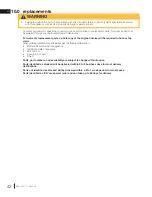
The auxiliary function controls the Night Light
TM
with dimmable control.
A. Use the Mode Key to guide you to the Night Light icon.
B. The intensity of the output can be adjusted through 6 levels.
Use the UP/DOWN arrow keys to adjust the output level.
A
single beep will confi rm reception of the command.
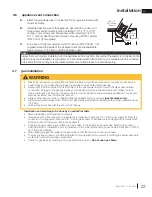
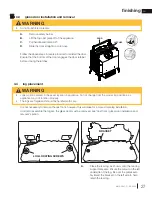
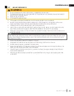
ADD TITLE: CONTINUOUS PILOT / INTERMITTENT PILOT (CPI / IPI) SELECTION
A. When the transmitter is in the “OFF” position, use the Mode Key to guide
you to the CPI mode icon.
B. Press the UP/DOWN to switch between IPI and CPI modes. A single BEEP
will confirm reception of the command.
Blue LCD Display
On / Off Key
Up / Down Arrow Key
Mode Key
Temperature Key
73
23
76
°F
68
Room Temperature
Set Temperature
76
°F
MAX
76
°F
OFF
76
°F
76
°F
76
°F
Hi
Flame Off
Flame at level 1
Flame at level 5
Flame at “Hi” level 6
76
°F
child lock
76
°F
OFF
76
°F
ON
76
°F
76
°F
68
76
°F
Hi
76
°F
OFF
76
°F
76
°F
IPI
76
°F
CPI
ON
SMART
°F
°C
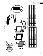
23.2_2
At any time in the sequence, the blower (if equipped) can be manually turned on/off using the remote
control.
note:
If the appliance is equipped with a CPI/IPI toggle switch, set the CPI/IPI to CPI
position to enable remote CPI operation. If the switch is set to IPI then it will
only work in IPI regardless of what is set on the remote control handset.
note:
Your remote system may have a built in timer (in thermostat mode) that enables the blower (if equipped) to cycle
on and off automatically when the burner turns on and off. With the remote control fan speed preset at the
preferred speed, the blower will come on approximately 5 minutes after the main burner comes on and will shut off
approximately 12 minutes after the burner shuts off.
This time delay is designed to maximize the blower distribution of heated air.
If at any time the burner re-ignites before the twelve minutes are over, the fan will continue to run.
ADD TITLE: TIMED BLOWER
ADD TITLE: CHILD PROOF FUNCTION
This function will lock the keys to avoid unsupervised operation.
A. Press the MODE and UP keys at the same time.
B. To de-activate this function, press the MODE and UP keys at the same time.
ADD TITLE: NIGHT LIGHT
The auxiliary function controls the AUX power outlet on the Control Module
which controls the NIGHT LIGHT™.
A. Use the Mode Key to guide you to the AUX icon.
B. Pressing the Up Arrow Key will activate the NIGHT LIGHT™.
C. Pressing the Down Arrow Key will turn the NIGHT LIGHT™ off. A single
“beep” will confirm the reception of the command.
Blue LCD Display
On / Off Key
Up / Down Arrow Key
Mode Key
Temperature Key
73
23
76
°F
68
Room Temperature
Set Temperature
76
°F
MAX
76
°F
OFF
76
°F
76
°F
76
°F
Hi
Flame Off
Flame at level 1
Flame at level 5
Flame at “Hi” level 6
76
°F
child lock
76
°F
OFF
76
°F
ON
76
°F
76
°F
68
76
°F
Hi
76
°F
OFF
76
°F
76
°F
IPI
76
°F
CPI
ON
SMART
°F
°C
The life span of the remote batteries depends on various factors: quality of the batteries, the
number of ignitions, etc.
When the transmitter batteries are low, a Battery Icon will appear on the LCD display before all
battery power is lost. When the batteries are replaced this icon will disappear.
When the receiver batteries are low, no “beep” will be emitted from the receiver when it
receives an ON/OFF command. This in an alert for the receiver that there’s low battery. When
the batteries are replaced the “beep” will be emitted from the receiver when the ON/OFF key is pressed.
If the batteries of the receiver or transmitter are low, the appliance can be turned on manually by sliding the three
position slider switch on the receiver to the “ON” position. This will bypass the remote control feature and the appliance
main burner will come on if the gas valve is in the “ON” position.
ADD TITLE: IN THE EVENT OF A POWER FAILURE
If the receiver is equipped with batteries they will enable flame height control or ON/OFF function to control the
appliance during a power failure. Blower and NIGHT LIGHT operation is not possible. Refer to “APPLIANCE
OPERATION” section when communications between receiver and transmitter have been lost. The receiver will emit
a “beep” sound to confirm programming has been successful once power is restored. During a power failure, if the
appliance was on, the flame height will stay at the setting prior to the failure. If off when the failure occurs and then
turned on, the flame height will come on at “HI”. The flame height can then be controlled by the remote.
ADD TITLE: LOW BATTERY / MANUAL BYPASS
ADD TITLE: Night Light Dimmer Control
Blue LCD Display
On / Off Key
Up / Down Arrow Key
Mode Key
Temperature Key
73
23
76
°F
68
Room Temperature
Set Temperature
76
°F
MAX
76
°F
OFF
76
°F
76
°F
76
°F
Hi
Flame Off
Flame at level 1
Flame at level 5
Flame at “Hi” level 6
76
°F
child lock
76
°F
OFF
76
°F
ON
76
°F
76
°F
68
76
°F
Hi
76
°F
OFF
76
°F
76
°F
IPI
76
°F
CPI
ON
SMART
°F
°C
The auxiliary function controls the Night Light
TM
with dimmable control.
A. Use the Mode Key to guide you to the Night Light icon.
B. The intensity of the output can be adjusted through 6 levels.
Use the UP/DOWN arrow keys to adjust the output level.
A
single beep will confirm reception of the command.
ADD TITLE: CONTINUOUS PILOT / INTERMITTENT PILOT (CPI / IPI) SELECTION
A. When the transmitter is in the “OFF” position, use the Mode Key to guide
you to the CPI mode icon.
B. Press the UP/DOWN to switch between IPI and CPI modes. A single BEEP
will confi rm reception of the command.
Blue LCD Display
On / Off Key
Up / Down Arrow Key
Mode Key
Temperature Key
73
23
76
°F
68
Room Temperature
Set Temperature
76
°F
MAX
76
°F
OFF
76
°F
76
°F
76
°F
Hi
Flame Off
Flame at level 1
Flame at level 5
Flame at “Hi” level 6
76
°F
child lock
76
°F
OFF
76
°F
ON
76
°F
76
°F
68
76
°F
Hi
76
°F
OFF
76
°F
76
°F
IPI
76
°F
CPI
ON
SMART
°F
°C
23.2_2
At any time in the sequence, the blower (if equipped) can be manually turned on/off using the remote
control.
note:
If the appliance is equipped with a CPI/IPI toggle switch, set the CPI/IPI to CPI
position to enable remote CPI operation. If the switch is set to IPI then it will
only work in IPI regardless of what is set on the remote control handset.
note:
7.6 night light dimmer control
EN
W415-2207 /
C
/
08.23.18
34
operation


