EN
W415-1299 / D /
12.03.14
22
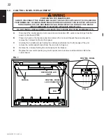
A.
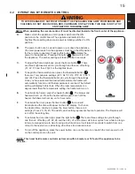
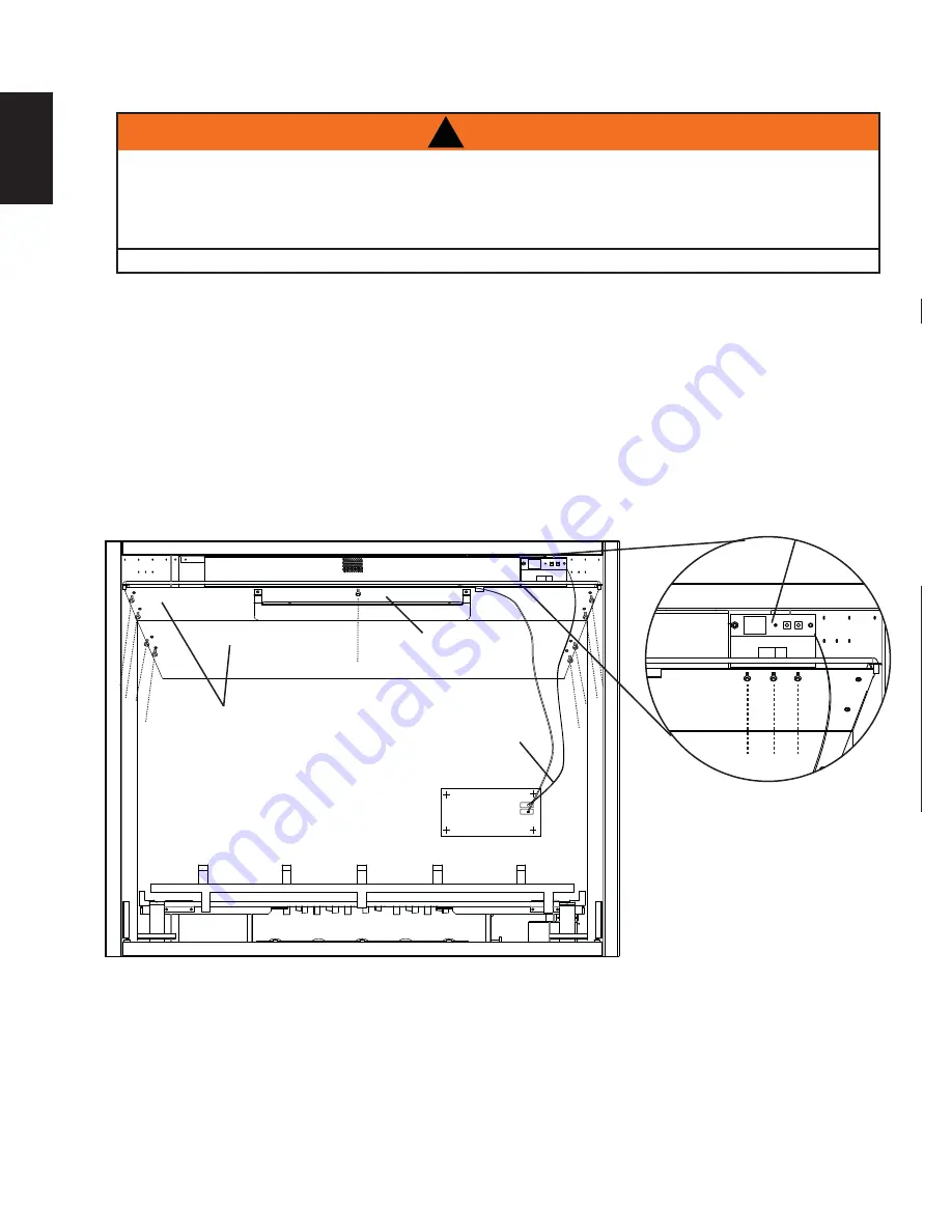
Disconnect the control panel remote receiver and decorative LED, quick connect plugs from the
power control board (PCB).
B.
Place one hand on the top rear panel and remove the 4 screws. Repeat the same process to
remove the 5 screws for the top front panel.
C.
Unscrew the 3 middle screws holding the control panel bracket on the front edge of the unit,
remove the control panel bracket from the unit, refer to Figure 2.
D.
Remove the 2 screws holding the control panel to the bracket.
E.
Replace the new control panel, plug control panel, remote receiver and decorative LED to the
control board.
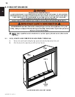
6.9 CONTROL PANEL REPLACEMENT
FIG. 1
CONTROL PANEL
FIG. 2
PANELS
PCB
CONTROL PANEL
LED CONNECTOR
!
WARNING
PREPARATION FOR MAINTENANCE
ALWAYS DISCONNECT THE POWER AND ALLOW THE ELECTRIC APPLIANCE TO COOL BEFORE
PERFORMING ANY CLEANING, MAINTENANCE OR RELOCATION OF THIS ELECTRIC APPLIANCE.
TURN CONTROLS TO OFF AND REMOVE PLUG FROM OUTLET OR TURN OFF THE HOUSE
CIRCUIT BREAKER TO ELECTRIC APPLIANCE RECEPTACLE.
DO NOT INSTALL REPLACEMENT LED LIGHTS THAT EXCEED SPECIFIED MAXIMUM WATTS.
DECORATIVE LED
LIGHT

