background image

W415-1285 / C / 05.12.16

32  

EN

DOOR

TOP OF

APPLIANCE

4” (101.6mm)

6” (152.4mm)

2” (50.8mm)

0” (0mm)

5” (127mm)


3”(76.2mm)

71.6

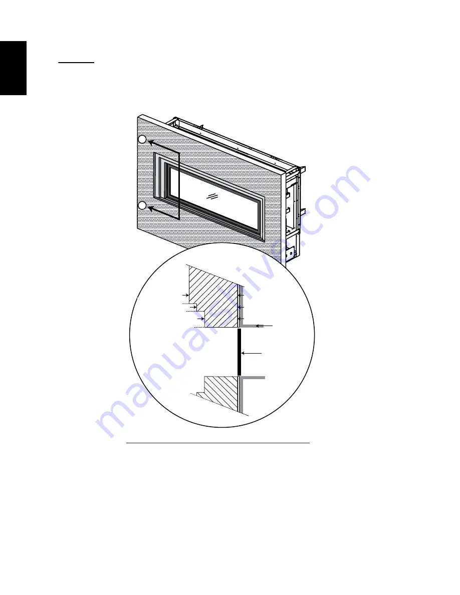
NON-COMBUSTIBLE FACING MATERIAL

WARNING: 

Non-combustible facing material must not project more than 4” (101.6mm) from the face of the 

door (all four sides). If greater projections are desired, increase the clearance to the sides and top by 2” 

(50.8mm) for every additional 1” (25.4mm) of projection. If using an optional surround, the same rule applies, 

starting from the top of the surround. Ensure clearances are maintained for surround removal, as it must lift 

off the appliance for maintenance.

DOOR

OPTIONAL 

SURROUND

TOP OF

APPLIANCE

4” (101.6mm)

6” (152.4mm)

2” (50.8mm)

0” (0mm)

5” (127mm)


3”(76.2mm)

B

B

A

A

SECTION A - A

SECTION B - B

DOOR

TOP OF

APPLIANCE

4” (101.6mm)

6” (152.4mm)

2” (50.8mm)

0” (0mm)

5” (127mm)


3”(76.2mm)

71.6

NON-COMBUSTIBLE FACING MATERIAL

WARNING: 

Non-combustible facing material must not project more than 4” (101.6mm) from the face of the 

door (all four sides). If greater projections are desired, increase the clearance to the sides and top by 2” 

(50.8mm) for every additional 1” (25.4mm) of projection. If using an optional surround, the same rule applies, 

starting from the top of the surround. Ensure clearances are maintained for surround removal, as it must lift 

off the appliance for maintenance.

DOOR

OPTIONAL 

SURROUND

TOP OF

APPLIANCE

4” (101.6mm)

6” (152.4mm)

2” (50.8mm)

0” (0mm)

5” (127mm)


3”(76.2mm)

B

B

A

A

SECTION A - A

SECTION B - B

FRONT OF 

APPLIANCE

DOOR

TOP OF

APPLIANCE

4” (101.6mm)

6” (152.4mm)

2” (50.8mm)

0” (0mm)

5” (127mm)


3”(76.2mm)

71.6

NON-COMBUSTIBLE FACING MATERIAL

WARNING: 

Non-combustible facing material must not project more than 4” (101.6mm) from the face of the 

door (all four sides). If greater projections are desired, increase the clearance to the sides and top by 2” 

(50.8mm) for every additional 1” (25.4mm) of projection. If using an optional surround, the same rule applies, 

starting from the top of the surround. Ensure clearances are maintained for surround removal, as it must lift 

off the appliance for maintenance.

DOOR

OPTIONAL 

SURROUND

TOP OF

APPLIANCE

4” (101.6mm)

6” (152.4mm)

2” (50.8mm)

0” (0mm)

5” (127mm)


3”(76.2mm)

B

B

A

A

SECTION A - A

SECTION B - B

4" (102mm)

5.4  NON-COmBuSTiBLE FACiNg mATEriAL

Summary of Contents for BHD4N

Page 1: ...lified installer service agency or the supplier This appliance may be installed in an aftermarket permanently located manufactured home USA only or mobile home where not prohibited by local codes this appliance is only for use with the type of gas indicated on the rating plate this appliance is not convertible for use with other gases unless a certified kit is used If the information in these inst...

Page 2: ...0 5 3 1 finishing support adjustment 31 5 4 non combustible facing material 32 5 5 alcove enclosure 33 5 6 minimum mantel clearances 34 5 7 nailing tab installation 34 6 0 finishing 35 6 1 side safety screen removal installation 35 6 2 end safety screen removal installation BHD4P only 36 6 3 door removal installation 37 6 4 control panel removal 38 6 5 end door removal installation BHD4P ONLY 38 6...

Page 3: ...antel see MINIMUM MANTEL CLEARANCES section SAFETY BARRIER 11 0 replacements 56 11 1 BHD4P Overview 57 11 2 BHD4st Overview 58 11 3 glass burner W100 0160 59 11 4 log cradle burner W100 0161 60 11 5 glaSS BURNER VALVE TRAIN ASSEMBLY 61 11 6 LOG BURNER VALVE TRAIN ASSEMBLY 62 12 0 accessories 63 13 0 troubleshooting 64 14 0 warranty 67 Batteries must be disposed of according to the local laws and r...

Page 4: ...ected before use and at least annually by a qualified service person More frequent cleaning may be required due to excessive lint from carpeting bedding material etc The appliance area must be kept clear and free from combustible materials gasoline and other flammable vapors and liquids Under no circumstances should this appliance be modified This appliance must not be connected to a chimney flue ...

Page 5: ...mm 1213 16 325mm 251 8 638mm RIGHT SIDE LEFT SIDE RIGHT SIDE LEFT SIDE 79 16 192mm ELECTRICAL INLET 79 16 192mm GAS INLET 21 16 53mm 343 16 868mm 45 1143mm 381 4 841mm 79 16 192mm ELECTRICAL INLET 79 16 192mm GAS INLET 21 16 53mm 8 203mm 5 127mm 251 8 638mm 1213 16 325mm SAFETY BARRIER SAFETY BARRIER 2 1 dimensions ...

Page 6: ...thout cutting a floor or roof joist If the appliance is installed directly on carpeting vinyl tile or other combustible material other than wood flooring the appliance shall be installed on a metal or wood panel extending the full width and depth Some appliances have optional fans or blowers If an optional fan or blower is installed the junction box must be electrically connected and grounded in a...

Page 7: ...und kits follow the framing instructions and the finishing instructions for removal of the top extension NOTE The protective wrap on plated parts is best removed when the assembly is at room temperature but this can be improved if the assembly is warmed using a hair dryer or similar heat source A barrier designed to reduce the risk of burns from the hot viewing glass is provided with the appliance...

Page 8: ... UNE COLONNE D EAU MINIMUM SUPPLY PRESSURE 11 WATER COLUMN D UNE COLONNE D EAU PRESSION D ALIMENTATION MINIMALE 7 0 WATER COLUMN D UNE COLONNE D EAU MAXIMUM SUPPLY PRESSURE 13 WATER COLUMN D UNE COLONNE D EAU PRESSION D ALIMENTATION MAXIMALE 67 9 P 4 67 9 SERIAL NUMBER NO DE SÉRIE BHD4 L APPAREIL DOIT ÉVACUER SES GAZ EN UTILISANT L ENSEMBLE D ÉVACUATION PROPRE A NAPOLEON RÉFÉRER AU MANUEL D INSTAL...

Page 9: ...ir intake vent pipes utilizing alternate constructions such as a chimney as part of the vent system is not permitted WARNING RISK OF FIRE MAINTAIN SPECIFIED AIR SPACE CLEARANCES TO VENT PIPE AND APPLIANCE IF VENTING IS INCLUDED WITH SPACERS THE VENT SYSTEM MUST BE SUPPORTED EVERY 3FT 0 9m FOR BOTH VERTICAL AND HORIZONTAL RUNS USE SUPPORTS OR EQUIVALENT NON COMBUSTIBLE STRAPPING TO MAINTAIN THE REQ...

Page 10: ...ctly above a sidewalk or paved driveway which is located between two single fam ily dwellings and serves both dwellings Local codes or regulations may require different clearances Do not allow the inside liner to bunch up on horizontal or vertical runs and elbows Keep it pulled tight A 1 31 8mm air gap all around between the inner liner and outer liner is required for safe operation pArT 5 8 SuppL...

Page 11: ...he appliance must have a minimum vertical rise off the appliance of 57 1448mm On all horizontal vent runs ensure that the vent pipe does not slope downward When terminating vertically the vertical rise is a minimum 36 914mm and a maximum 40 feet 12m above the appliance 40 FT 12m MAX 36 914mm MIN 16 MIN 406mm 43 1092mm MIN PLUS RISE 24 610mm MAX See VENTING section 43 1092mm ...

Page 12: ... a fireplace and 8 2 4m for a stove 9 5B Added metric dimensions 38 1 2 978mm MIN 24 610mm MIN REGARDLESS OF HORIZONTAL VENT LENGTH 12 305mm MIN TO GRADE 3 3 2 reduced vent clearance to combustibles The minimum clearances around the horizontal vent pipe to the combustible material may be reduced from 3 76 2mm 2 50 8mm to 1 25 4mm in installations with a minimum of 52 1320 8mm vertical rise made imm...

Page 13: ... 13 EN X3 3 4 1 2 USE MILL PAC TO SEAL ADAPTER to the APPLIANCE collarS X3 X3 5 6 USE MILL PAC TO SEAL THE INNER PIPE TO THE ADAPTER USE MILL PAC TO SEAL THE OUTER PIPE TO THE ADAPTER 3 4 converting from 5 8 to 4 7 venting ...

Page 14: ...a mechanical air supply inlet L 7 2 1m 7 2 1m Clearance above a paved sidewalk or paved driveway located on public property m 12 305mm 12 Clearance under a veranda porch or deck N 16 406mm 16 406mm Clearance above the roof O 2 0 6m 2 0 6m Clearance from an adjacent wall including neighbouring buildings p 8 2 4m 8 2 4m Roof must be non combustible without openings q 3 0 9m 3 0 9m See chart for wide...

Page 15: ...ntal run 3 times the vertical rise equal to or greater than the horizontal run maximum of 40 feet 12m maximum of 40 feet 12m 3 7 Definitions 14 2 For the following symbols used in the venting calculations and examples are greater than equal to or greater than less than equal to or less than HT total of both horizontal vent lengths Hr and offsets Ho in feet HR combined horizontal vent lengths in fe...

Page 16: ... 2 4m h1 2 5 FT 0 8m h2 2 FT 0 6m hr h1 h2 2 5 FT 0 8m 2 FT 0 6m 4 5 FT 1 4m hO 03 one 45 elbow two 90 elbows 135 03 225 135 2 7 FT 0 8m hT hr hO 4 5 FT 1 4m 2 7 FT 0 8m 7 2 FT 2 2m hT vT 7 2 FT 2 2m 8 FT 2 4m 15 2 FT 4 6m Formula 1 hT vT 7 2 FT 2 2m 8 FT 2 4m Formula 2 hT vT 40 FT 12 2m 15 2 FT 4 6m 40 FT 12 2m Since both formulas are met this vent configuration is acceptable 90 90 45 V1 H1 H4 90...

Page 17: ...vT 13 6 FT 4 2m 5 5 FT 1 7m 19 1 FT 5 8m Formula 1 hT 4 2FT 1 3m vT 4 2FT 1 3m vT 4 2 FT 1 3m x 5 5 FT 1 7m 23 1 FT 7m 13 6 FT 4 2m 23 1 FT 7M Formula 2 hT vT 24 75 FT 7 5m 19 1 FT 5 8m 24 75 FT 7 5m Since both formulas are met this vent configuration is acceptable 90 90 45 V1 H1 H4 90 90 H3 H2 V2 90 45 H1 H4 2 90 90 45 V1 H1 H2 REQUIRED VERTICAL RISE IN INCHES MILLIMETERS VT 0 5 1 5 15 4 6 20 6 1...

Page 18: ...Example V1 5 FT 1 5m V2 10 FT 3 1m VT V1 V2 5 FT 1 5m 10 FT 3 1m 15 FT 4 6m H1 3 FT 0 9m H2 2 5 FT 0 8m HR H1 H2 3FT 0 9m 2 5FT 0 8m 5 5 FT 1 7m HO 03 one 45 three 90 elbows 135 03 45 270 135 5 4 FT 1 6m HT HR HO 5 5 FT 1 7m 5 4 FT 1 m 10 9 FT 3 3m HT VT 10 9 FT 3 3m 15 FT 4 6m 25 9 FT 7 9m Formula 1 HT VT 10 9FT 3 3m 15 4 6m Formula 2 HT VT 40 FT 12 2m 25 9FT 7 9m 40 12 2m Since both formulas are...

Page 19: ...5 5 4 FT 1 6m HT HR HO 8FT 2 4m 5 4FT 1 6m 13 4FT 4 1m HT VT 13 4FT 4 1m 2 5FT 0 8m 15 9FT 4 8m Formula 1 HT 3VT 3VT 3FT 0 9m x 2 5FT 0 8m 7 5FT 2 3m 13 4 FT 4 1m 7 5 FT 2 3m Since this formula is not met this vent configuration is unacceptable Formula 2 HT VT 40 FT 12 2m 15 9FT 4 8m 40FT 12 2m Since only formula 2 is met this vent configuration in unacceptable and a new fireplace location or vent...

Page 20: ... INSIDE THE FIREBOX PRIOR TO HOOKING UP THE GAS AND ELECTRICAL SUPPLY IF YOUR APPLIANCE IS SUPPLIED WITH A REMOTE ENSURE THE REMOTE RECEIVER IS IN THE OFF POSITION PRIOR TO HOOKING UP THE GAS AND ELECTRICAL SUPPLY TO THE APPLIANCE FOR SAFE AND PROPER OPERATION OF THE APPLIANCE FOLLOW THE VENTING INSTRUCTIONS EXACTLY ALL EXHAUST AND INTAKE VENT PIPE JOINTS MUST BE SEALED USING RED RTV HIGH TEMP SIL...

Page 21: ... available from your authorized dealer distributor See accessories to order specific kits required A Determine the air terminal location cut and frame a square opening as illustrated in the ceiling and the roof to provide the minimum 1 25mm clearance between the vent pipe and any combustible material Try to center the vent pipe location midway between two joists to prevent having to cut them Use a...

Page 22: ...e joint connecting the inner flex pipe and the exhaust flue collar use only approved flexible vent pipe kits marked wolf Steel Approved venting as identified by the stamp only on the outer flex pipe 22 1a ELBOW SPACERS DO NOT ALLOW THE INNER FLEX PIPE TO BUNCH UP ON HORIZONTAL OR VERTICAL RUNS AND ELBOWS KEEP IT PULLED TIGHT SPACERS ARE ATTACHED TO THE INNER FLEX PIPE AT PREDETERMINED INTERVALS TO...

Page 23: ...to the exterior wall and make weather tight by sealing with caulking not supplied d If more vent pipe needs to be used to reach the fireplace couple them together as illustrated The vent system must be supported approximately every 3 feet 0 9m for both vertical and horizontal runs Use noncombustible strapping to maintain the minimum clearance to combustibles The air terminal mounting plate may be ...

Page 24: ...hing giving a 3 4 19mm margin all around Fasten to the roof Do not nail through the lower portion of the flashing Make weather tight by sealing with caulking Where possible cover the sides and top edges of the flashing with roofing material F Aligning the seams of the terminal and air terminal connector place the terminal over the air terminal connector making sure the vent pipe goes into the hole...

Page 25: ...horized dealer distributor 4 4 Mobile home installation 30 1a Installation and servicing to be done by a qualified installer Move the appliance into position and secure If equipped with a flex connector the appliance is designed to accept a 1 2 13mm gas supply Without the connector it is designed to accept a 3 8 9 5mm gas supply The appliance is equipped with a manual shut off valve to turn off th...

Page 26: ... SCREEN REMOVAL DOOR REMOVAL section B Remove media and media tray from the applaince see CRADLE BURNER REMOVAL section C Unscrew the 2 screws that hold the access panel to the firebox D Remove the gasket careful not to tear Gasket Access Panel 4 5 access panel for gas line connection ...

Page 27: ... RISK OF FIRE IN ORDER TO AVOID THE POSSIBILITY OF EXPOSED INSULATION OR VAPOUR BARRIER COMING IN CONTACT WITH THE APPLIANCE BODY IT IS RECOMMENDED THAT THE WALLS OF THE APPLIANCE ENCLOSURE BE FINISHED IE DRYWALL SHEETROCK AS YOU WOULD FINISH ANY OTHER OUTSIDE WALL OF A HOME THIS WILL ENSURE THAT CLEARANCE TO COMBUSTIBLES IS MAINTAINED WITHIN THE CAVITY DO NOT NOTCH THE FRAMING AROUND THE APPLIANC...

Page 28: ...raming dimensions are based on the finishing material supports position Framing may change depending on the finishing material thickness See FINISHING SUPPORT ADJUSTMENT section A MIN 22 5 8 575mm MAX 24 1 8 613mm B MIN 42 1 2 1080mm MAX 43 1 2 1105mm 5 1 framing 5 1 1 see thru framing bhd4st 5 1 2 peninsula framing bhd4p ...

Page 29: ...PORTANT The firestop assembly provided must be used when the vent pipes pass through any walls or are terminated horizontally If reduced to 4 7 venting a new firestop is required W010 3440 IMPORTANT The BHD4 requires a minimum inside enclosure height of 50 1270mm measured from the bottom of the appliance For temperature requirements this area must be left unobstructed COMBUSTIBLE NON COMBUSTIBLE B...

Page 30: ...c to allow for slight movement in the normal operation of the appliance If grout is used between the tiles a polymer based grout such as Mapei Ultracolour plus is recommended Primer Paint For a painted surface use a 100 acrylic latex primer and finish coat Paints may discolour THE SURFACE ABOVE THE APPLIANCE GETS VERY HOT IF PROPER FINISHING MATERIALS ARE NOT USED CRACKING CAN OCCUR 45 1143mm 38 1...

Page 31: ... adjusted by loosening the two screws SIDE VIEW NOTE Framing dimension A and B will be affected as the finishing supports are adjusted outwards refer to FRAMING section Finishing Material finish support Position 1 4 6mm 1 2 13mm 1 2 13mm 1 4 6mm 3 4 19mm Flush 0 0mm 1 4 Finishing Material 1 2 Finishing Material 3 4 Finishing Material 1 2 Combustible Board Finish support Finish support Finish suppo...

Page 32: ...by 2 50 8mm for every additional 1 25 4mm of projection If using an optional surround the same rule applies starting from the top of the surround Ensure clearances are maintained for surround removal as it must lift off the appliance for maintenance DOOR OPTIONAL SURROUND TOP OF APPLIANCE 4 101 6mm 6 152 4mm 2 50 8mm 0 0mm 5 127mm 3 76 2mm B B A A SECTION A A SECTION B B FRONT OF APPLIANCE DOOR TO...

Page 33: ...s to combustibles are maintained Non combustible material can be used provided the minimum clearances to combustible materials are applied The minimum enclosure volume must be increased by no less than the volume of the recess This adjustment can be made by increasing any or all of the height width and depth of the enclosure 71 2 ENCLOSURE AREA 5 5 alcove enclosure ...

Page 34: ...UR DE LA TABLETTE Ref Mantel Height Mantel Depth A B C D E 16 406 4mm 14 355 6mm 12 304 8mm 10 254mm 8 203 2mm 6 152 4mm F 0 0mm 2 50 8mm 4 101 6mm 6 152 4mm 8 203 2mm 10 254mm Ref G H I J K L M A N T E L H E I G H T MANTEL DEPTH 12 10 8 6 4 2 1 3 4 5 6 7 8 9 10 Ref Hauteur Plafondeur A B C D E 16 406 4mm 14 355 6mm 12 304 8mm 10 254mm 8 203 2mm 6 152 4mm F 0 0mm 2 50 8mm 4 101 6mm 6 152 4mm 8 203...

Page 35: ...NED TO PIVOT FORWARD WHEN RELIEVING EXCESS PRESSURE THAT MIGHT OCCUR FINISHING OR OTHER MATERIALS MUST NOT BE LOCATED IN THE OPENING SURROUNDING THE DOOR AS THIS WILL INTERFERE WITH THE DOORS ABILITY TO RELIEVE THE PRESSURE 72 6 SAFETY SCREEN SAFETY SCREEN A barrier designed to reduce the risk of burns from the hot viewing glass is provided with the appliance and must be installed Before the glass...

Page 36: ...ottom of the end screen retainer refer to Figure 1 B Pull the screen forward and out from the unit refer to Figure 2 FIG 1 NOTE A side screen must be removed prior to end screen removal see SIDE SCREEN REMOVAL section FIG 2 6 2 end safety screen removal installation BHD4P only ...

Page 37: ...ENINGS OPERATION OF LOUVRES OR DOORS OR ACCESS FOR SERVICE OBSERVE ALL CLEARANCES WHEN APPLYING COMBUSTIBLE MATERIALS BEFORE DOOR IS REMOVED TURN THE APPLIANCE OFF AND WAIT UNTIL APPLIANCE IS COOL TO THE TOUCH DOORS ARE HEAVY AND FRAGILE SO HANDLE WITH CARE 75 1 THIS WARNING FOR ELECTRICS ONLY A Remove screen see SCREEN REMOVAL section B Loosen but do not remove the 3 securing screws from the top ...

Page 38: ...ance refer to the DOOR REMOVAL INSTALLATION section B Remove the 6 screws securing the end door in place as shown below Ensure to keep one hand on the door from the inside of the appliance at all times to prevent it from falling C Tilt the door from the top downwards and carefully remove it from the appliance D To install the end door reverse these steps 6 screws NOTE Screens must be removed prior...

Page 39: ...he appliance refer to the DOOR REMOVAL INSTALLATION section B Place the 3 hearth pad on the pilot side of the burner as shown in Figure B C Place the 1A hearth pad on the right side and the 1 hearth pad on the left side of appliance as shown in Figure C D Place the two 2 hearth pads on the right and left sides as shown in Figure D E Place the 4 hearth pad on the left end as shown in Figure E B C D...

Page 40: ...ce onto the screw and spacer located in the corner of the burner on the right side Place a pin into the center of log 1 as shown in Figure 1 3 Place log 2 onto the pin located in the log 1 it should rest in the middle of the left side hearth pad as shown in Figure 2 Place one pin into the middle of log 2 as shown in Figure 2 4 Place log 3 onto the pin located in log 2 and let it rest on log 2 as s...

Page 41: ...n in Figure 10 Place one pin into log 1 as shown in Figure 10 12 Place log 11 onto the pin located in log 1 and let is rest on the right end hearth pad as shown in Figure 11 13 Place charcoal lump 12 onto the two pins located in the center of the burner as shown in Figure 12 14 Tear the ember material into small thin pieces and spread evenly on top of the burner Ember material will only glow when ...

Page 42: ...lacing around the burner CLEAN THE GLASS MEDIA PRIOR TO INSTALLATION BEFORE APPLYING THE CLEANED GLASS ENSURE THAT IT IS DRY DO NOT CHANGE OR SUBSTITUTE THE GLASS MEDIA MATERIAL PROVIDED WITH THIS APPLIANCE IF REPLACING USE ONLY THE REPLACEMENT GLASS MEDIA AVAILABLE FROM YOUR AUTHORIZED DEALER DISTRIBUTOR DO NOT PLACE ANY MEDIA GLASS OR VERMICULITE IN OR AROUND THE PILOT OPENING THIS WILL INTERFER...

Page 43: ...TER CALL A QUALIFIED SERVICE TECHNICIAN IMMEDIATELY TO HAVE THE APPLIANCE INSPECTED FOR DAMAGE TO THE ELECTRICAL CIRCUIT RISK OF ELECTRICAL SHOCK OR EXPLOSION DO NOT WIRE 110V TO THE VALVE OR TO THE APPLIANCE WALL SWITCH INCORRECT WIRING WILL DAMAGE CONTROLS ALL WIRING SHOULD BE DONE BY A QUALIFIED ELECTRICIAN AND SHALL BE IN COMPLIANCE WITH LOCAL CODES IN THE ABSENCE OF LOCAL CODES USE THE CURREN...

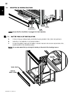
Page 44: ...ated in the control compartment of the appliance refer to the illustration below NOTE It is recommended that you change the battery at the start of the heating season WIRE NUTS 3 PRONG RECEPTACLE GROUND GREEN L2 WHITE L1 BLACK ELECTRICAL BOX CABLE CONNECTOR BATTERY HOUSING PANEL COVER CONTROL PANEL COVER NOTE Ensure that the transformer is plugged into the receptacle 7 2 receptacle wiring diagram ...

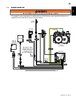
Page 45: ...C VALVE ORANGE GREEN GROUND EYELET ON OFF IPI CPI DISCONNECT THESE CONNECTIONS TO THE ON OFF SWITCH AND CONNECT TO AN OPTIONAL THERMOSTAT IPI BOARD DC SUPPLY TRANSFORMER VALVE ELECTRONIC OFF ON This appliance comes equipped with a battery back up If this back up is used install 4AA batteries not supplied into the holder and connect to the wire harness 7 4 wiring diagram ...

Page 46: ...THE PILOT AND MAIN BURNERS MUST BE DONE WITH THE GLASS DOOR OFF DO NOT CONNECT VALVE OR WALL SWITCH TO ELECTRICITY SEE INSTALLATION INSTRUCTIONS A THIS FIREPLACE IS EQUIPPED WITH AN IGNITION DEVICE WHICH AUTOMATICALLY LIGHTS THE PILOT DO NOT TRY TO LIGHT BY HAND B BEFORE OPERATING SMELL ALL AROUND THE FIREPLACE AREA FOR GAS AND NEXT TO THE FLOOR BECAUSE SOME GAS IS HEAVIER THAN AIR AND WILL SETTLE...

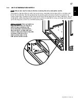
Page 47: ...nti condensation switch standing pilot is located in the control compartment Using your finger flip the switch up for standing pilot or down for intermittent pilot ignition Installer note Some jurisdictions may prohibit the use of a standing pilot In these jurisdictions the anti condensation switch shall be disconnected to comply with local codes To disconnect locate the white connector at the end...

Page 48: ... pressure can be checked the same as above using screw b Gauge should read as described on the chart below Check that main burner is operating on hI after taKiNg Pressure reaDiNgs Be sure to turN screws clocKwise firmly to reseal Do Not over torQue Leak test with a soap and water solution Prior to pilot adjustment ensure that the pilot assembly has not been painted If overspray or painting of the ...

Page 49: ... PILOT BURNER ELECTRODE FLAME SENSOR LA FLAMME DOIT ENVELOPPER LA PARTIE SUPÉRIEURE DE LA SONDE DE FLAMME DE 3 8 9 5mm À 1 2 12 7mm ÉLECTRODE LA SONDE DE FLAMME VEILLEUSE 3 8 1 2 9 5mm 12 7mm 54 1B 3 8 1 2 9 5mm 12 7mm FLAME MUST ENVELOP UPPER 3 8 9 5mm TO 1 2 12 7mm OF FLAME SENSOR PILOT BURNER ELECTRODE FLAME SENSOR LA FLAMME DOIT ENVELOPPER LA PARTIE SUPÉRIEURE DE LA SONDE DE FLAMME DE 3 8 9 5m...

Page 50: ...ot flame is large enough to engulf the flame sensor and or thermocouple thermopile as well as reaches the burner E Replace the cleaned logs rocks or glass Failure to properly position the media may cause carbon which can be distributed inside of firebox and on exterior surfaces surrounding vent termination F Check to see that the main burner ignites completely on all openings when turned on A 5 to...

Page 51: ...tions for pre cleaning Also gently remove any build up on the pilot assembly including if equipped thermopile thermocouple flame sensor and igniter NOTE Clean flame sensor using a fine emery cloth or a synthetic scrub pad such as Scotch Brite to remove any oxides Clean the pilot assembly using a vacuum with a soft brush attachment it is important that the pilot assembly is not painted Inspect all ...

Page 52: ... HOT GLASS WILL CAUSE BURNS DO NOT TOUCH GLASS UNTIL COOLED NEVER ALLOW CHILDREN TO TOUCH GLASS WARNING LA VITRE CHAUDE CAUSERA DES BRÛLURES NE PAS TOUCHER LA VITRE AVANT QU ELLE AIT REFROIDI NE JAMAIS LAISSER LES ENFANTS TOUCHER LA VITRE AVERTISSEMENT 10 2 glass Door replacement WARNING DO NOT USE SUBSTITUTE MATERIALS GLASS MAY BE HOT DO NOT TOUCH GLASS UNTIL COOLED CARE MUST BE TAKEN WHEN REMOVI...

Page 53: ...everse these steps NOTE When reinstalling the burner ensure that the venturi rests on the orifice D C A Remove the door s refer to the DOOR REMOVAL INSTALLATION section for instructions B Carefully remove the logs from the appliance C Remove all of the hearth pads from the appliance Refer to the HEARTH PAD INSTALLATION REMOVAL section for instructions D Remove the 4 screws securing the burner in p...

Page 54: ...ons B Carefully remove the glass or rocks from the appliance C To remove the media tray from the appliance lift the media tray and the media shelf up and out of the appliance The media tray and media shelf are secured together and resting loose in the firebox D Remove the 4 screws securing the burner in place as shown below Then slide the burner off the the orifice and remove from the appliance E ...

Page 55: ...nect the flex connector from the valve You may now lift the valve train out of the appliance 77 3 Vertical installations may display a very active flame If this appearance is not desirable the vent exit must be restricted using a restrictor vent kit Refer to ACCESSORIES in the REPLACEMENTS section for the appropriate kit This will reduce the velocity of the exhaust gases slowing down the flame pat...

Page 56: ...ENTiFiES iTEmS whiCh ArE NOT iLLuSTrATEd FOr FurThEr iNFOrmATiON CONTACT yOur AuThOriZEd dEALEr pArTS pArT NumBErS ANd AvAiLABiLiTy ArE SuBJECT TO ChANgE wiThOuT NOTiCE pArTS idENTiFiEd AS STOCKEd wiLL BE dELivErEd wiThiN 2 TO 5 BuSiNESS dAyS FOr mOST dELivEry dESTiNATiONS pArTS NOT idENTiFiEd AS STOCKEd wiLL BE dELivErEd wiThiN A 2 TO 4 wEEK pEriOd 41 2a FAILURE TO POSITION THE PARTS IN ACCORDANC...

Page 57: ... BOWL SHELF W710 0059 GLASS MEDIA TRAY W100 0161 LOG CRADLE BURNER W010 3207 LOG BURNER VALVE TRAIN ASSEMBLY W010 3206 GLASS BURNER VALVE TRAIN ASSEMBLY W100 0160 GLASS BURNER W565 0153 END SAFETY SCREEN W010 2829 DOOR LATCH ASSEMBLY X4 W010 3192 SCREEN RETAINER X2 W010 3205 DOOR ASSEMBLY X2 W565 0152 SAFETY SCREEN X2 W010 3204 SCREEN TRIM ASSEMBLY X2 W010 3209 RS VALVE ACCESS PANEL W010 3208 LS V...

Page 58: ...OR ASSEMBLY X2 W565 0151 SAFETY SCREEN X2 W475 0928 VALVE ACCESS PANEL X2 W080 1395 ACS SWITCH BRACKET W715 0191 ACS SWITCH W707 0010 TRANSFORMER W333 0024 SIDE HEARTH PAD 1A GL 686 GL 686 W333 0020 NOTCHED HEARTH PAD 1A GL 686 W333 0021 SIDE HEARTH PAD 1 GL 686 W333 0023 MIDDLE HEARTH PAD 2 X2 GL 686 W333 0022 END HEARTH PAD 4 GL 686 23 SAFETY SCREEN 16 13 13 14 15 16 17 18 14 FOR REPLACEMENT PAR...

Page 59: ...ITEMS MAY NOT APPEAR EXACTLY AS ILLUSTRATED 02 06 14 BHD4 GLASS BURNER W100 0160 REF NO PART NUMBER DESCRIPTION 1 W010 2954 BURNER ASSEMBLY 2 W080 1400 BURNER BRACKET X2 3 W290 0018 VENTURI GASKET 4 W720 0005 VENTURI 11 3 glass burner W100 0160 ...

Page 60: ...S ILLUSTRATED 02 06 14 BHD4 LOG CRADLE BURNER W100 0161 REF NO PART NUMBER DESCRIPTION 1 W010 2955 BURNER ASSEMBLY 2 W080 1244 BURNER BRACKET 3 W290 0018 VENTURI GASKET REF NO PART NUMBER DESCRIPTION 4 W720 0005 VENTURI 5 W080 1399 BURNER BRACKET 11 4 log cradle burner W100 0161 ...

Page 61: ...32 0103 GAS MANIFOLD 2 W456 0037 BURNER ORIFICE 37 3 W290 0157 MANIFOLD GASKET 4 W105 0001 BUSHING 5 W190 0029 CONTROL BOARD 6 W080 1366 VALVE BRACKET 7 W725 0065 VALVE REF NO PART NUMBER DESCRIPTION 8 W585 0790 PILOT HOUSING 9 W010 3024 PSE PILOT ASSEMBLY 10 W080 1304 PILOT BRACKET 11 W035 0337 VALVE TRAIN BASE 12 W200 0456 VALVE ACCESS COVER 13 W290 0247 ACCESS GASKET 11 5 glaSS BURNER VALVE TRA...

Page 62: ...32 0103 GAS MANIFOLD 2 W456 0037 BURNER ORIFICE 37 3 W290 0157 MANIFOLD GASKET 4 W105 0001 BUSHING 5 W190 0029 CONTROL BOARD 6 W080 1366 VALVE BRACKET 7 W725 0065 VALVE REF NO PART NUMBER DESCRIPTION 8 W350 0264 PILOT HOUSING 9 W010 3024 PSE PILOT ASSEMBLY 10 W080 1372 PILOT BRACKET 11 W035 0338 VALVE TRAIN BASE 12 W200 0456 VALVE ACCESS COVER 13 W290 0247 ACCESS GASKET 11 6 LOG BURNER VALVE TRAIN...

Page 63: ...E HARNESS GD826 7 LDAC DECORATIVE COIL REF NO PART NUMBER DESCRIPTION FRONT SIDE VIEW REAR SIDE VIEW 02 06 14 W135 0529 LOG 3 GL 686 W135 0530 LOG 4 GL 686 W135 0531 LOG 5 GL 686 W135 0532 LOG 6 GL 686 W135 0533 LOG 7 GL 686 W135 0534 LOG 8 GL 686 W135 0535 LOG 9 GL 686 W135 0536 LOG 10 GL 686 W135 0537 LOG 11 GL 686 W135 0540 CHARCOAL CHUNK 12 GL 686 W135 0528 LOG 2 GL 686 10 11 W135 0527 LOG 1 G...

Page 64: ... good transformer are between 6 2 and 7 0 volts A C battery backup if power is off Check batteries A shorted or loose connection Remove and reinstall the wiring harness that plugs into the module Remove and verify continuity of each wire in wiring harness Improper switch wiring Troubleshoot the system with the simplest ON OFF switch Module is not grounded Verify the valve and pilot assemblies are ...

Page 65: ...is will increase the flame rectification Verify correct pilot orifice is installed and inlet gas specifications to manual Remember the flame carries the rectification current not the gas If the flame lifts from pilot hood the circuit is broken A wrong orifice or to high of an inlet pressure can cause the pilot flame to lift The sensor rod may need cleaning Poor grounding between pilot assembly and gas ...

Page 66: ...ictor plate See RESTRICTING VENTS section if applicable Main burner flame is a blue lazy transparent flame blockage in vent Remove blockage In extreme conditions ice buildup may occur on the terminal and should be removed To minimize this from happening again it is recommended that the vent lengths that pass through unheated spaces attics garages crawl spaces be wrapped with an insulated mylar sle...

Page 67: ... plated trim or other components due to water weather damage long periods of dampness condensation damaging chemicals or cleaners will not be the responsibility of NAPOLEON All parts replaced under the President s Limited Lifetime Warranty Policy are subject to a single claim During the first 10 years NAPOLEON will replace or repair the defective parts covered by the lifetime warranty at our discr...

Page 68: ...places Outdoor Fireplaces Gas Grills Fireplaces Heating Cooling call 705 721 1212 Grills call 705 726 4278 napoleonproducts com 24 Napoleon Road Barrie Ontario Canada L4M 0G8 214 Bayview Drive Barrie Ontario Canada L4N 4Y8 103 Miller Drive Crittenden Kentucky USA 41030 7200 Trans Canada Highway Montreal Quebec Canada H4T 1A3 ...

Page 69: ...e mobile déjà instalée à demeure si les règlements locaux le permettent Cet appareil doit être utilisé uniquement avec le type de gaz indiqué sur la plaque signalétique Cet appareil ne peut être converti à d autres gaz sauf si une trousse de conversion est utilisée Si ces instructions ne sont pas suivies à la lettre un incendie ou une explosion pourraient s ensuivre causant des dommages matériels ...

Page 70: ...5 installation en alcÔve 101 5 6 DÉGAGEMENTS MINIMAUX DE LA TABLETTE 102 5 7 INSTALLATION DES SUPPORTS DE FIXATION 102 6 0 Finitions 103 6 1 RETRAIT de l écran de protection côté et l installation 103 6 2 RETRAIT de l écran de protection fin et l installation SEULEMENT bhd4p 104 6 3 installation enlèvement de la porte 105 6 4 enlèvement de PANNEAU DE CONTRÔLE 106 6 5 Enlèvement DE LA PORTE D EXTRÉ...

Page 71: ...ON MATÉRIAUX COMBUSTIBLES Évacuation voir la section ÉVACUATION Plaque d homologation voir la section INFORMATION SUR LA PLAQUE D HOMOLOGATION Porte voir la section INSTALLATION ENLÈVEMENT DE L ÉCRAN PORTE Porte voir la section INSTALLATION DE L ÉCRAN PORTE D EXTRÉMITÉ Ossature voir la section OSSATURE Tablette voir la section DÉGAGEMENTS MINIMAUX DE LA TABLETTE 11 0 rechanges 124 11 1 BHD4p VUE D...

Page 72: ...ère utilisation et au moins une fois l an par un spécialiste en entretien Un entretien plus fréquent pourrait être nécessaire en raison des peluches provenant des tapis literie etc L emplacement de l appareil doit être gardé libre de tous matériaux combustibles essence ou autres liquides et vapeurs inflammables Cet appareil ne devra être modifié en aucun cas Cet appareil ne doit pas être raccordé a...

Page 73: ... 1213 16 325mm 251 8 638mm 79 16 192mm 79 16 192mm 21 16 53mm 343 16 868mm 45 1143mm 381 4 841mm 79 16 192mm 79 16 192mm 21 16 53mm 8 203mm 5 127mm 251 8 638mm 1213 16 325mm ENTRÉEDU ÉLECTRIQUE ENTRÉEDU GAZ ENTRÉEDU ÉLECTRIQUE ENTRÉEDU GAZ CÔTÉ DROITE CÔTÉ GAUCHE CÔTÉ DROITE CÔTÉ GAUCHE ÉCRAN DE PROTECTION ÉCRAN DE PROTECTION ...

Page 74: ...areil est installé directement sur un tapis sur une surface de vinyle ou tout autre revêtement de plancher combustible autre que le bois l appareil devra être monté sur un panneau continu de métal ou de bois se prolongeant sur toute la largeur et la profondeur Certains appareils ont une soufflerie ou un ensemble de deux souffleries optionnel Si la soufflerie ou l ensemble de deux souffleries optionnel...

Page 75: ...xtension supérieure NOTE L emballage de protection sur les pièces plaquées s enlève mieux lorsque l assemblage est à température ambiante ou lorsqu il est chauffé avec un séchoir à cheveux ou une autre source de chaleur similaire Une barrière conçu à réduire le risque de brûlures à partir de le chaude la vitre est à condition que avec l appareil et sera être installés 67 9 HD4 Cote énergétique des...

Page 76: ...ANT PRODUIT DÉCORATIF NE PAS UTILISER COMME APPAREIL DE CHAUFFAGE DÉGAGEMENTS MINIMAUX DES MATÉRIAUX COMBUSTIBLES DESSUS 0 PLANCHER 0 CÔTÉS 0 ARRIÈRE 0 DESSUS DU CONDUIT D EVENT 3 CÔTÉS ET DESSOUS DU CONDUIT D EVENT 2 CONDUIT D EVENT VERTICAL 1 TABLETTE 8 DESSUS CÔTÉS ARRIÈRE SELON LES ESPACEURS DE DÉGAGEMENT POUR LES MATERIAUX D OSSATURE SELON LA MANUEL DE PROPRIÉTAIRE POUR LES MATÉRIAUX DE FINIT...

Page 77: ... évacuation et de prise d air se prolongent sur toute la longueur de la cheminée Toute autre méthode d installation telle que d utiliser la cheminée comme partie du système d évent est interdite AVERTISSEMENT RISQUE D INCENDIE CONSERVEZ LES DÉGAGEMENTS NÉCESSAIRES AU CONDUIT D ÉVENT ET À L APPAREIL SI LE SYSTÈME D ÉVENT EST FOURNI AVEC DES ESPACEURS LES COURSES HORIZONTALES ET VERTICALES DU SYSTÈM...

Page 78: ...ect Temp l American Metal Amerivent et le Metal Fab suivez la procédure d installation se trouvant sur le site Internet du fournisseur Pour les systèmes d évents dont le conduit intérieur d évacuation possède déjà des joints scellés seuls les joints du conduit extérieur de prise d air doivent être scellés avec un scellant de silicone rouge à haute température RTV Ce même scellant peut être utilisé...

Page 79: ...ement à la sortie de l appareil d un minimum de 57 pouces 1448mm Sur toutes les courses horizontales assurez vous que la pente des conduits d évent ne soit pas descendante Quand elle se termine verticalement l élévation verticale est d un minimum de 36 pouces 914mm et d un maximum de 40 pieds 12m au dessus de l appareil Voir la section ÉVACUATION 40 FT 12m MAX 36 914mm MIN 16 MIN 406mm 43 1092mm M...

Page 80: ... de l évent est de 10 pieds 3m pour un foyer et 8 pieds 2 4m pour un poêle 9 5b 12 305mm MIN AU NIVEAU DU SOL 38 1 2 978mm MIN 24 610mm MIN INDÉPENDAMMENT DE LA LONGUEUR D ÉVENT HORIZONTAL 3 3 2 matériaux combustibles d Évents réduits Les dégagements minimum authour de l évent horizontale au matériqux combustible peut être réduit de 3 76 2mm 2 50 8mm à 1 25 4mm dans les installation avec une cours...

Page 81: ...vacuation de 5 8 À 4 7 utiliser le SCELLANT mill pac Pour sceller l INTÉRIEUR du conduit À l adaptateur utiliser le SCELLANT mill pac Pour sceller l adaptateur aux colliers de l appareil utiliser le SCELLANT mill pac Pour sceller l exTÉRIEUR du conduit À l adaptateur ...

Page 82: ...murs adjacents incluant les maisons voisines p 8 2 4m 8 2 4m Le toit doit être incombustible et sans ouvertures q 3 0 9m 3 0 9m Voir le tableau pour les dimensions d un mur plus large r 6 1 8m 6 1 8m Voir le tableau pour les dimensions d un mur plus profond La terminaison ne doit pas être installée sur quelconque mur ayant une ouverture entre la terminaison et le côté ouvert de la structure s 12 3...

Page 83: ...plus grande ou égale à la course horizontale 3 fois la course verticale plus grande ou égale à la course horizontale éVAcuAtion sur le dessus 3 7 LÉGENDE 14 2 Les symboles suivants sont utilisés dans le calcul et les exemples d évacuation plus grand que plus grand ou égal à plus petit que plus petit ou égal à Ht total de la longueur des courses horizontales Hr plus la valeur des déviations Ho en p...

Page 84: ... évacuation exige plus qu un coude de 45 et de 90 les formules suivantes s appliquent Formule 1 HT VT Formule 2 HT VT 40 pieds 12 2m Exemple V1 8 PI 2 4m VT V1 8 PI 2 4m H1 2 5 PI 0 8m H2 2 PI 0 6m HR H1 H2 2 5PI 0 8m 2PI 0 6m 4 5 PI 1 4m HO 0 03 un coude 45º deux coudes 90º 135 0 03 225 135 2 7 PI 0 8m HT HR HO 4 5 PI 1 4m 2 7 PI 0 8m 7 2 PI 2 2m HT VT 7 2 PI 2 2m 8 PI 2 4m 15 2 PI 4 6m Formule 1...

Page 85: ... 4 2 Vt 4 2 Vt 4 2 PI 1 3m x 5 5 PI 1 7m 23 1 PI 7m 13 6 PI 4 2m 23 1 PI 7m Formule 2 Ht Vt 24 75 PI 7 5m 19 1 PI 5 8m 24 75 PI 7 5m Puisque les deux formules sont respectées cette configuration d évacuation est acceptable H4 2 90 90 45 V1 H1 H2 COURSE VERTICALE REQUISE EN POUNCES MILLIMETERS VT 0 5 1 5 15 4 6 20 6 1 100 2540 50 1270 150 3810 12 5 3 8 57 1447 8 147 3733 8 10 3 1 0 2 5 0 8 5 1 5 7 ...

Page 86: ...40 pieds 12 2m Exemple V1 5 PI 1 5m V2 10 PI 3 1m VT V1 V2 5 PI 1 5m 10 PI 3 1m 15 PI 4 6m H1 3 PI 0 9m H2 2 5 PI 0 8m HR H1 H2 3 PI 0 9m 2 5 PI 0 8m 5 5 PI 1 7m HO 0 03 un coude 45º trois coudes 90º 135º 0 03 45 270 135 5 4 PI 1 6m HT HR HO 5 5 PI 1 7m 5 4 PI 1 6m 10 9 PI 3 3m HT VT 10 9 PI 3 3m 15 PI 4 6m 25 9 PI 7 9m Formule 1 HT VT 10 9PI 3 3m 15PI 4 6m Formula 2 HT VT 40 PI 12 2m 25 9PI 7 9m ...

Page 87: ...70 135 5 4 PI 1 6m HT HR HO 8 PI 2 4m 5 4 PI 1 6m 13 4 PI 4 1m HT VT 13 4 PI 4 1m 2 5 PI 0 8m 15 9 PI 4 8m Formule 1 HT 3VT 3VT 3PI 0 9m x 2 5PI 0 8m 7 5PI 2 3m 13 4PI 4 1m 7 5PI 2 3m Puisque cette formule n est pas respectée cette configuration d évacuation est inacceptable Formule 2 HT VT 40 PI 12 2m 15 9PI 4 8m 40 PI 12 2m Puisque seulement la formule 2 est respectée cette configuration est ina...

Page 88: ...W573 0007 NON FOURNI À L EXCEPTION DU RACCORDEMENT DU CONDUIT D ÉVACUATION À LA BUSE DE L APPAREIL QUI DOIT ÊTRE SCELLÉ AVEC LE SCELLANT MILL PAC SI VOUS UTILISEZ DES COLLIERS POUR TUYAU POUR RACCORDER LES COMPOSANTS D ÉVACUATION VOUS DEVEZ AUSSI INSTALLER TROIS VIS POUR VOUS ASSURER QUE LE RACCORDEMENT NE SE DÉFASSE PAS NE SERREZ PAS LA GAINE FLEXIBLE RISQUE D INCENDIE D EXPLOSION OU D ASPHYXIE S...

Page 89: ...ntre le conduit d évacuation et l espaceur coupe feu c Dans le grenier faites glisser le collet de conduit d évacuation vers le bas afin de recouvrir l extrémité ouverte du protecteur de conduit d évacuation et serrez Ceci empêchera tout matériau tel que l isolant de remplir l espace vide de 1 po 25 4mm autour de l évent 21 1b CALFEUTRAGE PROTECTEUR DU CONDUIT D ÉVACUATION ESPACEUR COUPE FEU FACE ...

Page 90: ... être scellé avec le scellant Mill Pac W573 0007 non fourni N utilisez que les ensembles certifiés de gaines flexibles portant l inscription 22 1 COUDE ESPACEURS NE LAISSEZ PAS LA GAINE FLEXIBLE SE TASSER CONTRE LES COURSES HORIZONTALES OU VERTICALES ET LES COUDES GARDEZ LA TENDUE DES ESPACEURS SONT FIXÉS À LA GAINE FLEXIBLE À INTERVALLES PRÉDÉTERMINÉS AFIN DE GARDER UN ESPACE VIDE AVEC LE CONDUIT ...

Page 91: ...aines dans le coupe feu tout en conservant le dégagement nécessaire aux matériaux combustibles En soutenant la terminaison les inscriptions étant à l endroit et lisibles fixez la terminaison au mur extérieur et rendez la étanche en la silicone rouge W573 0002 non fourni d Si plus de sections de gaine doivent être utilisées pour atteindre l appareil raccordez les ensemble tel qu illustré Le système...

Page 92: ...n centré dans le solin en laissant une marge de 3 4 19 1mm tout autour Fixez le au toit Ne clouez pas à travers la partie inférieure du solin Imperméabilisez le en le scellant avec du calfeutrage Si possible recouvrez les côtés et le bord supérieur du solin avec des matériaux de couverture F Alignez les joints de la terminaison et du connecteur de terminaison et placez la terminaison par dessus le...

Page 93: ...r un installateur qualifié A Mettez l appareil en place et fixez le b Si l appareil est muni d un raccord flexible celui ci est conçu pour recevoir une conduite de gaz de 1 2 Sans raccord flexible l appareil est conçu pour recevoir une conduite de gaz de 3 8 L appareil est muni d une soupape d arrêt manuelle pour fermer l alimentation en gaz c Branchez le gaz en conformité avec les codes locaux En l...

Page 94: ...É ET L INSTALLATION B Enlevez les composants décoratif et le plateau du l appareil voir la section ENLÈVEMENT DU BRÛLEUR POUR ROCHES C Dévissez les deux vis qui fixent le panneau d accès de l appareil D Enlevez le joint d étanchéité ne pas déchirer 4 5 PANNEAU D ACCÈS POUR LA CONDUITE DE GAZ Joint D étanchéité Panneau D accès ...

Page 95: ...IT RESPECTER LA HAUTEUR MINIMALE REQUISE MESUREZ À PARTIR DE LA BASE DE L APPAREIL SI DES ENSEMBLES DE MONTANTS EN ACIER AVEC PANNEAU DE CIMENT SONT FOURNIS OU SPÉCIFIÉ DANS LES INSTRUCTIONS D INSTALLATION ILS DOIVENT ÊTRE INSTALLÉS SI SPÉCIFIÉ DANS LES INSTRUCTIONS D INSTALLATION LES MATÉRIAUX DE FINITION DOIVENT ÊTRE NON COMBUSTIBLES PLACER ÉCLAT AVEC LE FACE DE L APPAREIL ÉTENDUE DU SOMMET DE L...

Page 96: ...sature sont basés sur la position du support de finition L ossature peut changer dépendant de l épaisseur du matériaux de finition Voir la section ADJUSTEMENT DE LA SUPPORT DE FINITIONS 45 1 2 1156mm 46 1 2 1181mm A A MIN 22 5 8 575mm MAX 24 1 8 613mm 46 1 2 1181mm A B A MIN 22 5 8 575mm MAX 24 1 8 613mm B MIN 42 1 2 1080mm MAX 43 1 2 1105mm ...

Page 97: ...enceinte un dégagement de 3 76mm est requis entre le haut du conduit d évacuation et les matériaux combustibles Pour tout autre dégagement à l intérieur de l enceinte y compris l endroit où le conduit d évacuation sort de l enceinte l espacement requis est de 2 51mm à partir des côtés et du bas de 3 76mm à partir du haut pour les sections horizontales et de 2 51mm pour les sections verticales Cons...

Page 98: ...arreaux et du coulis Nous recommandons d utiliser des carreaux à joints secs et de les installer à l aide d un mortier à deux composantes avec un additif au latex acrylique tel que Mapei Kerabond Kerlastic pour permettre un léger mouvement lors du fonctionnement normal de l appareil Si du coulis est utilisé entre les carreaux un coulis à base de polymère tel que Mapei Ultracolour plus est recomman...

Page 99: ...c une support de fin qui peut être ajusté en desserrant les deux vis VUE DU CÔTÉ NOTE Dimension A et B de l ossature sera affecté quand les supports de finitions sont adjuster vers l extérieur Voir la section OSSATURE matériaux de finition Position du support de finition 1 4 6mm 1 2 13mm 1 2 13mm 1 4 6mm 3 4 19mm Flush 0 0mm 1 2 Panneau de combustible B A 1 1 2 38mm MAX 1 2 13mm MIN 1 1 2 38mm MAX...

Page 100: ...ections plus grandes sont requises augmentez les dégagements des côtés et du dessus de 2 50 8mm pour chaque pouce 24 5mm supplémentaire de projection Si vous utilisez un moulure optionelle les même règles s applique commençant du sommet du moulure Garantir que les dégagements sont maintenus pour l enlèvement du moulure vous devez l enlever de l appareil pour l entretien PORTE MOULURE OPTIONELLE SO...

Page 101: ...x matériaux combustibles sont respectés Vous pouvez utiliser un matériau incombustible pourvu que les dégagements minimaux aux matériaux combustibles soient appliqués Le volume minimal de l enceinte doit être augmenté d au moins la valeur du volume de la zone encastrée Cet ajustement peut être réalisé en augmentant une ou toutes les dimensions de l enceinte 71 2 ZONE ENCEINTE 5 5 installation en a...

Page 102: ... 102mm B 8 203mm 6 152mm A 10 254mm 8 203mm L A T A B L E T T E H A U T E U R D E PROFONDEUR DE LA TABLETTE Ref Mantel Height Mantel Depth A B C D E 16 406 4mm 14 355 6mm 12 304 8mm 10 254mm 8 203 2mm 6 152 4mm F 0 0mm 2 50 8mm 4 101 6mm 6 152 4mm 8 203 2mm 10 254mm Ref G H I J K L M A N T E L H E I G H T MANTEL DEPTH 12 10 8 6 4 2 1 3 4 5 6 7 8 9 10 Ref Hauteur Plafondeur A B C D E 16 406 4mm 14 ...

Page 103: ...RTURE DE L APPAREIL L ASSEMBLAGE DE LA PORTE EST CONÇUS POUR PIVOTER VERS L AVANT DE L ÉVACUATION D UN SURPLUS DE PRESSION QUI POURRAIT SURVENIR LES MATÉRIAUX DE FINITION OU TOUT AUTRE MATÉRIAU NE DOIVENT PAS EMPIÉTER SUR L OUVERTURE ENTOURANT LA PORTE PUISQU IL NUIRONT AU FONCTIONNEMENT DE LA PORTE LORS DE L ÉVACUATION D UN SURPLUS DE PRESSION 72 6 6 1 RETRAIT de l écran de protection côté et l i...

Page 104: ...EMENT bhd4p NOTE La côté de l écran doit être enlevée avant de mettre fin à l enlèvement de l écran A Enlevez le 4 vis située sur le supérieure et inférieur de la retenue de l écran de fin référer Figure 1 B Tirez l ecran vers l avant et l extérieur de l appareil référer Figure 2 FIG 1 FIG 2 ...

Page 105: ...ERROUILLÉS NE FAITES PAS FONCTIONNER L APPAREIL LORSQUE LES LOQUETS SONT DÉVERROUILLÉS LES MATÉRIAUX DE FAÇADE ET DE FINITION NE DOIVENT PAS NUIRE À LA CIRCULATION DE L AIR DANS LES OUVERTURES D AIR ET LES PERSIENNES NI AU FONCTIONNEMENT DES PERSIENNES OU DES PORTES ILS NE DOIVENT PAS NON PLUS ENTRAVER L ACCÈS POUR L ENTRETIEN RESPECTEZ TOUS LES DÉGAGEMENTS AUX MATÉRIAUX COMBUSTIBLES AVANT D ENLEV...

Page 106: ...s NOTE L écran doit être enlevée avant de mettre fin à l enlèvement de l écran référer la section RETRAIT de l écran de côté et l installation A Enlevez les portes principales de l appareil Pour ce faire reportez vous à la section ENLÈVEMENT ET INSTALLATION DES PORTES B Enlevez les 6 vis qui retiennent la porte d extrémité comme illustré ci dessous Pour empêcher la porte de tomber retenez la en to...

Page 107: ...la section installation enlèvement de la porte pour les instructions d enlèvement B Placer la base de protection 3 à la côté du pilote comme illustrée en Figure B C Placer la base de protection 1A à la côté droite et la base de protection 1 à la côté gauche de l appareil comme illustrée en Figure C D Placer les deux bases de protection 2 aux côtés droite et gauche comme illustrée en Figure D E Pla...

Page 108: ...pour les instructions d enlèvement 2 Placer bûche 1 sur l épingle aux coin du bruleur et l épingle aux base de protection à la côté gauche Placer une épingle au centre de la bûche 1 comme illustrée en Figure 1 3 Placer bûche 2 sur l épingle en bûche 1 il devrait se reposer sur le milieu de la base de protection à la côté droite comme illustrée en Figure 2 Placer une épingle au centre de la bûche 2...

Page 109: ... bûche 1 comme illustrée en Figure 10 12 Placer bûche 11 sur l épingle en bûche 1 il devrait se reposer sur la base de protection à la côté gauche comme illustrée en Figure 11 13 Placer la morceau de charbon 12 sur les deux épingles au centre du bruleur comme illustrée en Figure 12 14 Déchirez les braises incandescentes en petits morceaux placez les sur le brûleur Les braises seront incandescentes...

Page 110: ...à fond et laissez les sécher NETTOYEZ LES BRAISES VITRIFIÉES AVANT L INSTALLATION ASSUREZ VOUS QU ELLES SONT SÈCHES AVANT DE LES DISPOSER DANS LE PLATEAU NE CHANGEZ PAS OU NE SUBSTITUEZ PAS LES BRAISES VITRIFIÉES FOURNIES AVEC CET APPAREIL EN CAS DE REMPLACEMENT N UTILISEZ QUE LES BRAISES VITRIFIÉES DE RECHANGE DISPONIBLES CHEZ VOTRE DÉTAILLANT AUTORISÉ SEULEMENT ÉTALER UNE COUVERTURE MINCE DE BRA...

Page 111: ... CANADIEN DE L ÉLECTRICITÉ CSA C22 1 AU CANADA OU LE NATIONAL ELECTRICAL CODE ANSI NFPA 70 AUX ÉTATS UNIS ALLUMEZ TOUJOURS LA VEILLEUSE QUE CE SOIT POUR LA PREMIÈRE FOIS OU LORSQUE L APPROVISIONNEMENT EN GAZ EST ÉPUISÉ AVEC LA PORTE VITRÉE OUVERTE OU RETIRÉE 69 2 6 9 mise en place du logo 7 0 branchement électrique 7 1 branchement par câble Vous devez effectuer un branchement par câble avec cet ap...

Page 112: ...cter le sauvegarde de piles au connecteur de pile situé dans le compartment de contrôle de l appareil comme illustrée ci dessous NOTE Il est recommandé que vous changez les piles au début de la saison de chauffage NOTE Garantir que le transformateur est connecté à la réceptacle CAPUCHONES DE CONNEXION RÉCEPTACLE À TROIS BROCHES TERRE VERT L2 BLANC L1 NOIR BOÎTE ÉLECTRIQUE CONNECTEUR SAUVEGARDE DE ...

Page 113: ...RDEZ PAS L INTERRUPTEUR MURAL OU LA SOUPAPE DE GAZ À L ALIMENTATION ÉLECTRIQUE 110 VOLTS BOÎTIER DE PILES FOURNI AUX SAC DU MANUEL TERRE DFC SOUPAPE ON OFF IPI CPI ALIMENTATION CC OFF ON ORANGE VERT CARTE DE CIRCUITS IMPRIMÉS IPI SOUPAPE ÉLECTRONIQUE ANNEAU DE MISE À LA TERRE INTERRUPTER ACS IPI Débranchez ces connecteurs de l interrupteur marche arrêt pour les connecter au thermostat optionnel TR...

Page 114: ...ALL A QUALIFIED SERVICE TECHNICIAN FORCE OR ATTEMPTED REPAIR MAY RESULT IN A FIRE OR EXPLOSION D DO NOT USE THIS FIREPLACE IF ANY PART HAS BEEN UNDER WATER IMMEDIATELY CALL A QUALIFIED SERVICE TECHNICIAN TO INSPECT THE FIREPLACE AND REPLACE ANY PART OF THE CONTROL SYSTEM AND ANY GAS CONTROL WHICH HAS BEEN UNDER WATER ATTENTION NE PAS ALLUMER SI DES ENFANTS OU D AUTRES INDIVIDUS À RISQUE SONT À PRO...

Page 115: ... anticondensation veilleuse permanente est situé au centre du panneau de commande Avec le doigt basculez l interrupteur vers le haut pour le mode veilleuse permanente ou vers le bas pour le mode allumage intermittent de la veilleuse note D installeur Certains juridictions peuvent interdire avec l utilisation d une veilleuse permanente Dans ces juridictions l interrupteur anticondensation seront dé...

Page 116: ... pour enlever la peinture sur la hotte de la veilleuse sur l électrode et sur le capteur de flamme 39 7A 3 8 1 2 9 5mm 12 7mm FLAME MUST ENVELOP UPPER 3 8 9 5mm TO 1 2 12 7mm OF FLAME SENSOR PILOT BURNER ELECTRODE FLAME SENSOR LA FLAMME DOIT ENVELOPPER LA PARTIE SUPÉRIEURE DE LA SONDE DE FLAMME DE 3 8 9 5mm À 1 2 12 7mm ÉLECTRODE LA SONDE DE FLAMME VEILLEUSE PILOT BURNER ELECTRODE FLAME SENSOR 3 8 ...

Page 117: ...TRODE LA SONDE DE FLAMME VEILLEUSE 54 1b Il est important d effectuer périodiquement une inspection visuelle de la flamme de la veilleuse et du brûleur Comparez les à ces illustrations Si des flammes paraissent anormales contactez un technicien de service 3 8 1 2 9 5mm 12 7mm FLAME MUST ENVELOP UPPER 3 8 9 5mm TO 1 2 12 7mm OF FLAME SENSOR LA FLAMME DOIT ENVELOPPER LA PARTIE SUPÉRIEURE DE LA SONDE...

Page 118: ...ante pour envelopper la sonde de flamme et ou le thermocouple thermopile et qu elle atteigne le brûleur e Remettez en place les bûches les roches ou la vitre nettoyées si équipé Omettre de positionner les composants décoratifs adéquatement peut causer des dépots de carbone qui peuvent se déposer à l intérieure de la chambre de combustion et sur les surfaces extérieures entourant d évent F Vérifiez ...

Page 119: ...nlevez aussi tout dépôt se trouvant sur l assemblage de la veilleuse et aussi s il y a lieu sur la thermopile le thermocouple le capteur de flamme et l allumeur NoTE vous devrez nettoyer le capteur de flamme à l aide d une morceau de de laine d acier ou un tampon récurage Scotch Brite afin de retirer toute trace d oxydation Nettoyez l assemblage du pilote à l aide d un aspirateur muni d une brosse ...

Page 120: ...E CHAUDE CAUSERA DES BRÛLURES NE PAS TOUCHER LA VITRE AVANT QU ELLE AIT REFROIDI NE JAMAIS LAISSER LES ENFANTS TOUCHER LA VITRE AVERTISSEMENT 10 2 REMPLACEMENT DE LA VITRE PORTE A Placez le cadre de porte face vers le bas en prenant soin de ne pas égratigner la peinture B Centrez la vitre avec joint d étanchéité à l intérieur du cadre de porte en plaçant le côté épais du joint face vers le haut C ...

Page 121: ...ur puis enlèvez le de l appareil E Pour re installer le brûleur renverser ces étapes NOTE En réinstallant le brûleur garantir que le venturi se repose sur l injecteur A Enlèver les porte s por les instruction voir la section installation enlèvement de la porte B Soigneusement enlèver les bûches de l appareil C Enlèver tous les bases de protection de l appareil comme illustrée ci dessous Voir la se...

Page 122: ...te B Soigneusement emlèver les roches ou braises vitrifiées de l appaeril C Enlèver les 4 vis qui obtienne le plateau puis enlèver le plateau et l étage du plateau hors de l appareil comme illutrée ci dessous D Enlèver les 4 vis qui obtienne le brûleur comme illustré ci dessous Glissez le brûleur hors de l injecteur puis enlèvez le de l appareil E Pour re installer le brûleur renverser ces étapes ...

Page 123: ...e Vous pouvez maintenant retirer l assemblage de la soupape de l appareil 77 3 Certaines configurations d évacuation verticales peuvent avoir une flamme très active Si cette apparence n est pas désirée la sortie du conduit d évacuation doit être réduite en utilisant une plaque de restriction Pour obtenir l ensemble approprié voir les ACCESSOIRES à la section RECHANGES Ceci diminuera la vélocité des...

Page 124: ...dentiFie les Articles qui ne sont pAs illustrés pour plus d inFormAtion contActeZ Votre détAillAnt Autorisé piÈces numéro des piÈces et si il soit disponibilité peut chAnger sAns préAVis pArties identiFiées comme gArnie seront liVrés dAns 2 À 5 Jours pour lA plupArt des destinAtions de liVrAison piÈces non identiFiées que stocKés seront liVrés dAns un délAi de 2 À 4 semAines 41 2A OMETTRE DE POSIT...

Page 125: ...S DE SOUPAPE W080 1395 SUPPORT DU INTERRUPTEUR ACS W715 0191 INTERRUPTEUR ACS W707 0010 TRANSFORMATEUR W333 0024 BRIQUE DE PLANCHER DE CÔTÉ 1A GL 686 W333 0020 BRIQUE DE PLANCHER ENTAILLÉE 1A GL 686 W333 0021 BRIQUE DE PLANCHER DE CÔTÉ 1 GL 686 W333 0023 BRIQUE DE PLANCHER CENTRALE 2 X2 GL 686 W333 0022 BRIQUE DE PLANCHER D EXTRÉMITÉ 4 GL 686 13 14 23 24 25 19 26 27 14 6 4 3 8 1 7 2 5 1 2 5 3 4 5 ...

Page 126: ... ACS W707 0010 TRANSFORMATEUR W333 0024 BRIQUE DE PLANCHER DE CÔTÉ 1A GL 686 GL 686 W333 0020 BRIQUE DE PLANCHER ENTAILLÉE 1A GL 686 W333 0021 BRIQUE DE PLANCHER DE CÔTÉ 1 GL 686 W333 0023 BRIQUE DE PLANCHER CENTRALE 2 X2 GL 686 W333 0022 BRIQUE DE PLANCHER D EXTRÉMITÉ 4 GL 686 23 16 13 13 14 15 16 17 18 14 L ECRAN DE PROTECTION POUR LES PIÉCES DE REMPLACEMENT VOIR BRÛLEUR VERRE L ASSEMBLAGE DE LA...

Page 127: ...T NO DESCRIPTION 1 W010 2954 ASSEMBLAGE DE BRÛLEUR 2 W080 1400 SUPPORT DE BRÛLEUR X2 3 W290 0018 JOINT D ÉTANCHÉITÉ DE VENTURI 4 W720 0005 VENTURI CES ARTICLES PEUT DIFFÉRER DE CELLE ILLUSTRÉE ROCHES BRÛLEUR W100 0161 03 05 16 11 3 VERRE BRÛLEUR W100 0160 ...

Page 128: ...955 ASSEMBLAGE DE BRÛLEUR 2 W080 1244 SUPPORT DE BRÛLEUR 3 W290 0018 JOINT D ÉTANCHÉITÉ DE VENTURI REF NO PART NO DESCRIPTION 4 W720 0005 VENTURI 5 W080 1399 SUPPORT DE BRÛLEUR CES ARTICLES PEUT DIFFÉRER DE CELLE ILLUSTRÉE VERRE BRÛLEUR W100 0160 03 05 16 11 4 ROCHES BRÛLEUR W100 0161 ...

Page 129: ...PANNEAU DE CONTRÔLE 6 W080 1366 SUPPORT DU SOUPAPE 7 W725 0065 SOUPAPE REF NO PART NO DESCRIPTION 8 W585 0790 BOÎTIER DE VEILLEUSE 9 W010 3024 ASSEMBLAGE DE VEILLEUSE PSE 10 W080 1304 SUPPORT DE VEILLEUSE 11 W035 0337 BASE DU SOUPAPE 12 W200 0456 COUVERCLE D ACCÈS SOUPAPE 13 W290 0247 JOINT D ÉTANCHÉITÉ D ACCÈS CES ARTICLES PEUT DIFFÉRER DE CELLE ILLUSTRÉE L ASSEMBLAGE DE LA SOUPAPE DU VERRE BRÛLE...

Page 130: ... W190 0029 PANNEAU DE CONTRÔLE 6 W080 1366 SUPPORT DU SOUPAPE 7 W725 0065 SOUPAPE REF NO PART NO DESCRIPTION 8 W350 0264 9 W010 3024 ASSEMBLAGE DE VEILLEUSE PSE 10 W080 1372 11 W035 0338 BASE DU SOUPAPE 12 W200 0456 13 W290 0247 JOINT D ÉTANCHÉITÉ D ACCÈS COLLECTEUR DU JOINT D ÉTANCHÉITÉ SUPPORT DE VEILLEUSE BOÎTIER DE VEILLEUSE CES ARTICLES PEUT DIFFÉRER DE CELLE ILLUSTRÉE COUVERCLE D ACCÈS SOUPA...

Page 131: ...FACE VUE DU ARRIERE 14 15 13 2 18 2 21 2 19 5 20 17 2 4 23 22 12 23 15 14 13 16 19 2 22 2 12 21 18 17 W135 0529 BÛCHES 3 GL 686 W135 0530 BÛCHES 4 GL 686 W135 0531 BÛCHES 5 GL 686 W135 0532 BÛCHES 6 GL 686 W135 0533 BÛCHES 7 GL 686 W135 0534 BÛCHES 8 GL 686 W135 0535 BÛCHES 9 GL 686 W135 0536 BÛCHES 10 GL 686 W135 0537 BÛCHES 11 GL 686 W135 0540 MORCEAUX DE CHARBON DE BOIS 12 GL 686 W135 0528 BÛCH...

Page 132: ...n desserrée ou causant un court circuit Retirez et réinstallez le harnais de fils qui se branche dans le module Retirez et vérifiez la continuité de chaque fil dans le harnais de fils Filage d interrupteur inapproprié Réparez le système avec un simple interrupteur MARCHE ARRÊT Le module n est pas mis à la terre Vérifiez si les assemblages de la veilleuse et de la soupape sont bien mis à la terre a...

Page 133: ...pe la tige de la sonde Ceci augmentera le redressement du courant de la flamme Vérifiez si le bon injecteur de veilleuse est installé et que l alimentation en gaz est conforme aux spécifications du manuel Souvenez vous que la flamme transporte le courant redresseur et non le gaz Si la flamme se détache de la hotte le circuit est rompu Un mauvais injecteur ou une pression d arrivée trop élevée peut ca...

Page 134: ...lieu La flamme du brûleur principal est bleue paresseuse et transparente Système d évacuation bloqué Enlevez ce qui obstrue Dans des conditions de froid extrême une accumulation de glace peut se former sur la terminaison et devrait être enlevée lorsque nécessaire pour minimiser les chances que cela survienne de nouveau il est recommandé que les évents qui passent à travers des espaces non chauffés ...

Page 135: ...s composants par l eau les dommages causés par les intempéries de longues périodes d humidité la condensation des produits chimiques ou produits d entretien nuisibles ne seront pas la responsabilité de NAPOLÉON Toutes les pièces remplacées en vertu de la politique de Garantie à vie limitée du Président ne peuvent faire l objet que d une seule réclamation Durant les dix premières années NAPOLÉON re...

Page 136: ...s électriques Foyers extérieurs Grils à gaz de qualité Foyers Chauffage et Climatisation Grils composez 514 737 6294 napoleonproducts com 7200 Route Transcanadienne Montréal Québec H4T 1A3 24 Napoleon Road Barrie Ontario Canada L4M 0G8 214 Bayview Drive Barrie Ontario Canada L4N 4Y8 103 Miller Drive Crittenden Kentucky USA 41030 ...

Reviews: