W415-1789 / C / 01.29.19
EN
20
7.0 remote inline pre-installation
note:
The air damper assembly must be closed when the blower is not running for the system to function correctly.
Fig. 1
Fig. 2
Fig. 3
Blower housing assembly
illustrated on its side.
For remote inline installations, you must follow the instructions below before beginning installation. For exterior and
remote exterior installations, see “exterior & remote exterior pre-installation” section.
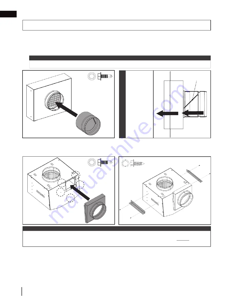
1. Install the air damper assembly onto the collar of the hot air exhaust assembly and secure with self-drilling screws
(supplied)
(Fig. 1)
. Rotate so that the air damper assembly closes shut when the blower is not running.
2. Attach the 6” (152mm) collar connector assembly to the blower housing assembly using self-drilling screws (sup-
plied)
(Fig. 2).
3. Attach the mounting brackets to the blower housing assembly using screws (supplied)
(Fig. 3).
FOR REMOTE INLINE INSTALLATIONS ONLY
x 5
#9-14 Thread, RH
Hex
x 4
x 3
The plate of
the air damper
assembly must
open from the
bottom. Take
care to install
in the correct
orientation so it
will open when
the blower op-
erates. Always
test before
finishing.
IMPOR
TANT
Plate
note:
If desired, grills other than those supplied with the
DHC™ Plus
may be used for remote inline installations. In
those instances, ensure to maintain a free area of 73.9 sq. in. (47680 sq. mm) minimum and
always
install the
damper.
Blower housing assembly
illustrated on its side.
Profile View
4. Attach the inline cover assembly using screws (supplied). See “electrical information” section for more details.


