EN
W415-1789 / C / 01.29.19
21
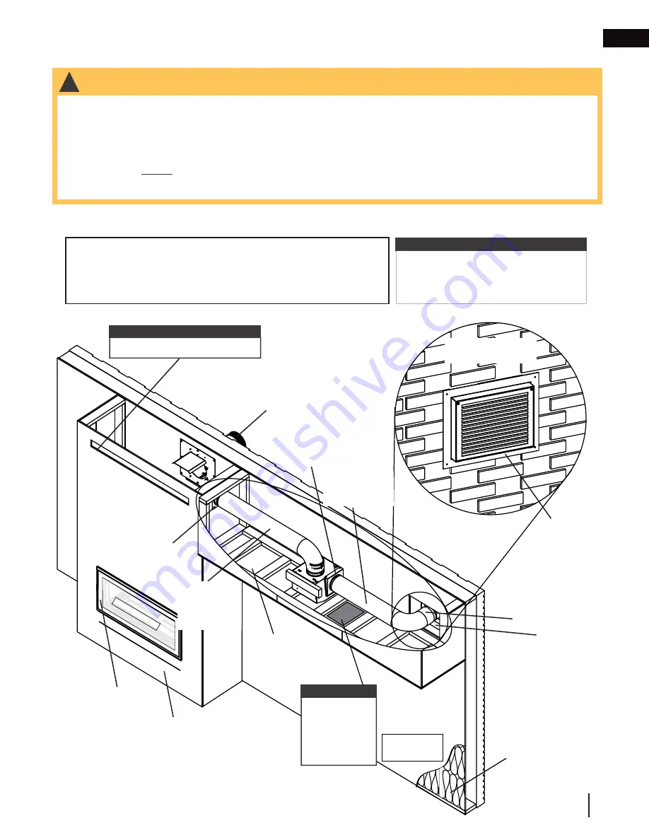
8.0 remote inline installation
DHC™ Plus
remote inline installation can be installed inline anywhere between the appliance enclosure and the
hot air exhaust assembly with a total vent length up to 60’ (18.2m).
Inside View of
Bulkhead (Some
Framing and
Finishing Hidden
for Clarity)
L
VX38 Illustrated
GLASS GUARD
Maintain
distance to
combustibles.
View of Opposite
Exterior Wall
note:
MUST have air outlet opening.
Enclosure
Appliance
Collar Plate
Assembly
6” Steel
Duct
(Not
Supplied)
6” Rigid Steel
Venting (Not
Supplied)
Air Damper
Assembly
Hot Air Exhaust
Assembly
Wall
Flashing
Interior
Exterior
6” Collar
Connector
Assembly
Appliance Vent
Terminal (if
applicable)
8.1
remote inline installation overview
note:
Diagram is for illustrative purposes
only. Installation must comply with all
electrical and local codes.
• DHCP-BK
• DHCP-HK
Required:
!
WARNING
note:
MUST have
access panel
for service or
maintenance of
blower.
• Minimum clearance to combustibles must be maintained or a serious fire hazard could result.
• DO NOT cover or place any items in the
Dynamic Heat Control™
air outlet opening. Failure to comply with
these instructions will create a fire hazard.
•
DHC™ Plus CANNOT be mounted directly above or below the appliance vent terminal as this will
cause the system to fail. It MUST be mounted to the left or right of the appliance vent terminal.
• For optimal performance, we recommend installing
DHC™ Plus
within the top 12” (30.5cm) of the enclosure.
However, it MUST be installed above the appliance.
• The minimum height requirement above the appliance will vary depending on the appliance size. See “minimum
venting requirements” section of your appliance manual for details.
• Venting, 6” rigid steel (not supplied)
• Duct, steel 6” (not supplied)
Insulation


