W415-1789 / C / 01.29.19
EN
24
remote inline installation
8.3
ducting installation
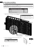
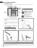
1. Determine the location for the 6” (152mm) collar plate assembly on the appliance enclosure, and then cut a 6”
(152mm) diameter hole
(Fig. 1)
.
Top of Enclosure
12”
(30.5cm)
Air Outlet
Opening
Ø 6”
(152mm)
Fig. 1
Left Side Profile View
Interior
Exterior
2. Secure the 6” (152mm) collar plate assembly over
the hole with the appropriate fasteners (not supplied)
(Fig. 2)
.
3. Install 6” steel ducting (not supplied) from the appli-
ance enclosure to the blower housing assembly inlet
(Fig. 3)
.
4. Install 6” rigid steel venting (not supplied) from the
blower housing assembly outlet to the hot air ex-
haust assembly
(Fig. 4)
.
note:
Ensure to maintain 1” (25mm) clearance to
combustibles.
Fig. 3
Fig. 4
Inside View of
Bulkhead (Some
Framing and
Finishing Hidden
for Clarity)
Inside View of
Bulkhead (Some
Framing and
Finishing Hidden
for Clarity)
Fig. 2
note:
Ensure to create the Ø 6” (152mm)
hole within the top 12” (30.5cm) of the
enclosure
(Fig. 1)
.
Access
Panel
Access
Panel
No materials of any type
permitted in this area with
the exception of an approved
appliance vent system or the
DHC™ Plus
system.
note:
When constructing a bulkhead, particularly one that passes through multiple rooms or spaces, always ensure that
you adhere to all local building codes and requirements.
Recommended
DHC™ Plus
collar plate assembly installation
zone (12” [30.5cm]).


