EN
W415-1789 / C / 01.29.19
27
electrical information
Fig. 3
note:
Ensure to use armoured cable, connectors, and strain reliefs suitable for installation (not supplied).
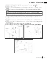
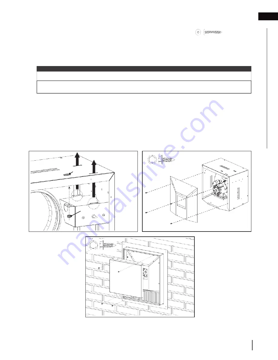
8. If applicable, remove the 4 screws securing the inline cover assembly and set them aside
(Fig. 3)
. Remove
the inline cover assembly and set it aside.
9. Install the on/off switch into the on/off switch housing with 2 screws (supplied).
10. Install the pal nut and knob.
11. Install the new armoured cable from the SIT control board to the on/off switch housing inside the blower kit
housing.
12. Connect the hot wire of the new armoured cable to one end of the on/off switch inside the on/off switch
housing.
#10 Thread, RH
29/64”
1/8”
1-1/2”
Quadrex Drive
x2
Armoured cable should be installed in a stud whenever possible. Armoured cable should also be installed as
close to the outside of the enclosure and as far away from the appliance as possible.
13. Connect the opposite end of the on/off switch to the black wire from the blower inside the on/off switch
housing.
14. Connect the neutral wire of the new armoured cable to the white wire from the blower inside the on/off switch
housing.
15. Connect the ground wires from the blower and armoured cable to the ground screw inside the on/off switch
housing.
16. Install the on/off switch housing into the blower kit housing by inserting the tabs into the slots
(Fig. 2)
. Tighten
the nut onto the stud.
17. Install/reinstall the inline cover assembly using 4 screws (supplied)
(Fig. 3)
.
18. Install/reinstall the decorative cover onto the blower housing assembly using 4 screws (supplied)
(Fig. 4)
.
#9-14 Thread, RH
Hex
0.348”
x 4
Fig. 2
Some components
hidden for clarity.
#9-14 Thread, RH
Hex
0.348”
x 4
Fig. 4
Nut
Stud


