background image

23

W415-0763 / B / 10.28.11

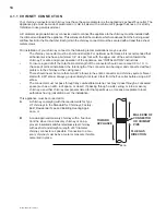
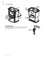
Provisions have been made on the stove to install an optional blower kit (EP62-1) that comes complete with 
a variable speed switch to turn the blower on and off, as well as adjusting the blower speed. An optional 
thermostatic sensor control kit, EP36, to thermally activate the blower is also available.

Drywall dust will penetrate into the blower bearings, causing irreparable damage. Care must be taken to 
prevent drywall dust from coming into contact with the blower or its compartment. Any damage resulting from 
this condition is not covered by the warranty policy.

Use of the blower increases the output of heat.

Attach the mounting bracket to the blower assembly. Then attach the mounting bracket to the back of your 
appliance, push on the variable speed knob and plug into any grounded electrical outlet.

Do not remove the knock out on the back of the appliance.

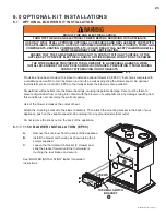
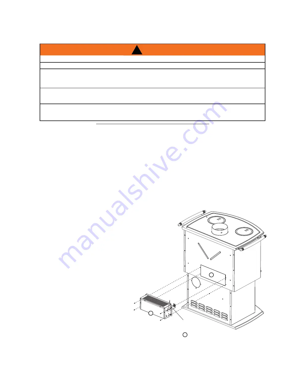
6.0 OPTIONAL KIT INSTALLATIONS

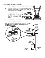
A. 

Remove the knock-out from the back of the appliance.

B. 

Install the blower and housing as shown using the 4 
screws supplied.

C. 

Loosen the thermal switch bracket (2 screws) and 
slide the bracket forward until the thermodisc is 
touching the rear fi rebox and secure.

See “BLOWER INSTALLATION” leafl et for detailed 
instructions.

1

2

3

THERMAL SWITCH

BRACKET

SCREWS

KNOCK-OUT

BLOWER

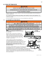
6.1  OPTIONAL BLOWER KIT INSTALLATION

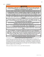
6.1.1 1150 BLOWER INSTALLATION (EP65)

!

WARNING

RISK OF FIRE AND ELECTRICAL SHOCK.

TURN OFF THE GAS AND ELECTRICAL POWER BEFORE SERVICING THIS APPLIANCE.

USE ONLY WOLF STEEL APPROVED OPTIONAL ACCESSORIES AND REPLACEMENT PARTS WITH 

THIS APPLIANCE. USING NON-LISTED ACCESSORIES (BLOWERS, DOORS, LOUVRES, TRIMS, GAS 

COMPONENTS, VENTING COMPONENTS, ETC.) COULD RESULT IN A SAFETY HAZARD AND WILL 

VOID THE WARRANTY AND CERTIFICATION.

ENSURE THAT THE FAN’S POWER CORD IS NOT IN CONTACT WITH ANY SURFACE OF THE 

APPLIANCE TO PREVENT ELECTRICAL SHOCK OR FIRE DAMAGE. DO NOT RUN THE POWER 

CORD BENEATH THE APPLIANCE.

THE WIRE HARNESS PROVIDED IN THE BLOWER KIT IS A UNIVERSAL HARNESS. WHEN 

INSTALLED, ENSURE THAT ANY EXCESS WIRE IS CONTAINED, PREVENTING IT FROM MAKING 

CONTACT WITH MOVING OR HOT OBJECTS.

51.5

Summary of Contents for EPA 1100

Page 1: ...ding or fire authority and follow their guidelines Operate only with the door tightly closed Burn wood behind the log retainer directly on the firebricks Do not use an elevated grate or otherwise rais...

Page 2: ...8 5 0 FINISHING 19 5 1 DOOR REMOVAL INSTALLATION 19 5 2 DOOR AND HANDLE INSTALLATION 19 5 3 ORNAMENTAL TRIVET INSTALLATION 20 5 4 PEDESTAL TRIM INSTALLATION IF SUPPLIED 20 5 5 BRICKS AND BAFFLE INSTAL...

Page 3: ...KIT INSTALLATION section Handle see DOOR AND HANDLE INSTALLATION section Draft see AIR CONTROL section Door see DOOR REMOVAL INSTALLATION section Rating plate see RATING PLATE INFORMATION section 145...

Page 4: ...y screen or guard removed for servicing must be replaced prior to operating the appliance Under no circumstances should this appliance be modified This appliance must not be connected to a chimney flu...

Page 5: ...7ft3 1 7ft3 2 25ft3 3 0ft3 APPROX AREA HEATED 600 1500 ft2 600 1500 ft2 1000 2000 ft2 1000 3500 ft2 HEAT OUTPUT HIGH BURN 55 000 BTU 55 000 BTU 70 000 BTU 85 000 BTU DURATION LOW FIRE 7 Hours 7 Hours...

Page 6: ...THOROUGHLY BEFORE STARTING YOUR INSTALLATION AND FOLLOW THEM CAREFULLY THROUGHOUT YOUR PROJECT WARNING Before beginning your installation consult with your local building code agency or fire officials...

Page 7: ...er of fibre baffles at the top to maintain a high tem perature in the combustion chamber so that gases mixing with the preheated air from the secondary air manifold tube are easily ignited and burned...

Page 8: ...TEMENT SUR L TRE AVERTISSEMENT RISQUE D CHAPPEMENT DE FUM E TENIR LA PORTE FERM E LORSQUE LE PO LE FONCTIONNE REMPLACEZ LA VITRE PAR UNE VITRE EN C RAMIQUE SEULEMENT NE SURCHAUFFEZ PAS L APPAREIL SI L...

Page 9: ...CE BOTTOM EXCLUDING HEARTH HEIGHT WARNING BACK WALL B SIDE WALL A BACK WALL C SIDE WALL F D E E PARALLEL CORNER SINGLE WALL CONNECTOR DOUBLE WALL CONNECTOR 1100 1150 1400 1450 1900 1100 1400 1450 1900...

Page 10: ...in the house Other devices are present that exhaust house air The house has tight fitting windows and or is equipped with a well sealed vapour barrier WARNING IF ROOM AIR STARVATION OCCURS BECAUSE THE...

Page 11: ...knockout in the pedestal back or through a hole in the floor to line up with the hole in the pedestal base Use a fresh air kit Secure the 4 inch diameter aluminum liner by flaring the end once it is...

Page 12: ...E THE POSSIBILITY OF APPLIANCE SMOKING OR AIR FLOW REVERSAL THE OUTSIDE AIR INLET MUST REMAIN CLEAR OF LEAVES DEBRIS ICE AND OR SNOW IT MUST BE UNRE STRICTED WHILE APPLIANCE IS IN USE TO PREVENT ROOM...

Page 13: ...URE STRUCTURAL INTEGRITY IS NOT COMPROMISED FIRESTOP SPACERS MUST BE USED WHENEVER THE CHIMNEY PENETRATES A CEILING FLOOR AREA THE TOTAL HORIZONTAL VENT LENGTH SHOULD NOT EXCEED 40 OF THE CHIMNEY HEIG...

Page 14: ...tical installation the total length of the connector can be longer and connected without problem to the chimney at the ceiling level There should never be more than two 90 elbows in the entire connect...

Page 15: ...ney must extend at least 3 feet above its point of contact with the roof and at least 2 feet higher than any wall roof building or obstacle within 10 feet horizontally 59 1A 3 FT MIN 3 FT MIN 3 FT MIN...

Page 16: ...hat the chimney passes through If your chimney system is enclosed within the attic area a rafter radiation shield is required C Hold a plumb bob from the underside of the roof to determine where the o...

Page 17: ...or any specific requirements Consult with your dealer regarding special connection components available for use for wall pass throughs Use only parts that have been tested and listed for use in a wall...

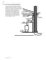
Page 18: ...you are using a masonry chimney it is important that it be built in compliance with the specifications of the Building Code in your region It must normally be lined with fire clay bricks metal or clay...

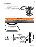
Page 19: ...install the door PINS 5 1 DOOR REMOVAL INSTALLATION 5 2 DOOR AND HANDLE INSTALLATION DOOR HANDLE NUT DOOR HANDLE LATCH LOCK WASHER DOOR SPACER SPRING WASHER FRONT VIEW NOTE Position of door handle lat...

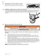
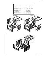
Page 20: ...into place for your appliance as illustrated A Install the bottom bricks working from the back of the appliance forward B Before installing the back bricks loosen the screw holding the brick retainer...

Page 21: ...J A A A A A A A A A A A A A A A A A A A A A B B B B G H E F A A C C B B D D Brick Retainers 9 x 2 x 19 5 8 Fibre Baffles W018 0130 X2 J A 1 1 4 x 4 1 2 x 9 F 1 1 4 x 2 1 2 x 6 1 8 B 1 1 4 x 3 x 9 G 1...

Page 22: ...illustrated from the preferred side of the stove rear Secure the lid lifter hook as illustrated facing out to the side or bend it towards the back LID LIFTER HOOK LID LIFTER HANDLE FIREBOX CAST TOP O...

Page 23: ...f the appliance B Install the blower and housing as shown using the 4 screws supplied C Loosen the thermal switch bracket 2 screws and slide the bracket forward until the thermodisc is touching the re...

Page 24: ...will reduce the firebox temperature and result in an unsatisfactory burn Remember it is more efficient to burn medium sized wood briskly and refuel frequently than to load the appliance with large log...

Page 25: ...optimum temperature Reopen the door and or draft control to re establish a brisk fire The other problem may have been wet wood The typical symptom is sizzling wood and moisture being driven from the...

Page 26: ...with the ash dump door blocked open or a poor gasket seal on the main door 93 1 A flash fire is a small fire burned quickly when you don t need much heat After your kindling has caught load at least...

Page 27: ...ash pan when transporting the ashes to a closed container with a tight fitting lid for storage Carry the ash pan using the front and back handles REAR FOLDING HANDLE TO OPEN PULL AND ROTATE ASH WELL C...

Page 28: ...orrect fuel or small fuel pieces which would normally be used as kindling Leaving the door ajar too long and creating extreme temperatures as the air rushes in the open door Burning your appliance wit...

Page 29: ...e chimney is cold NOTE Appliances burned consistently without hot fires may result in significant creosote accumulations in the chimney Certain items and considerations are important in chimney cleani...

Page 30: ...prints or other marks from the plated surfaces before operating the appliance for the first time Use a glass cleaner or vinegar and towel to clean If not cleaned properly before operating for the firs...

Page 31: ...has cracks in the end grain Cut the wood so that it will fit horizontally front to back making for easier loading and less of a likelihood that the wood will roll onto the glass Manufactured firelogs...

Page 32: ...77 W018 0077 N A N A N A BAFFLE FIBRE J N A N A W018 0078 W018 0078 W018 0130 BAFFLE FIBRE 12 W135 0238 W135 0238 W135 0238 N A W135 0238 CAST ASH LIP 13 W010 0347 W010 0347 W010 0347 W010 0347 W010 0...

Page 33: ...W N A H222 GW DOOR GOLD EARLY AMERICAN 39 H222 SSW H222 SSW H222 SSW N A H222 SSW DOOR BRUSHED STAINLESS STEEL EARLY AMERICAN 40 W010 1071 W010 1071 W010 1071 W010 1071 W010 1071 DOOR GLASS WITH GASKE...

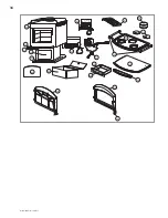
Page 34: ...34 W415 0763 B 10 28 11 27 20 45 30 32 33 34 40 38 16 25 39 35 29 28 13 12 15 24 26 17 36...

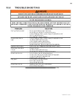
Page 35: ...kage Inspect chimney Smokes when door is open Cold air blockage Burn a piece of paper to establish a draft Insufficient draft Add more pipe Let air stabilize before opening door Ensure baffles are pos...

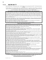
Page 36: ...sibility of NAPOLEON NAPOLEON reserves the right to have its representative inspect any product or part thereof prior to honouring any warranty claim All parts replaced under the President s Limited L...

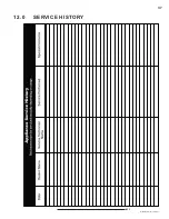
Page 37: ...37 W415 0763 B 10 28 11 43 1 12 0 SERVICE HISTORY...

Page 38: ...38 W415 0763 B 10 28 11 13 0 NOTES 44 1...

Page 39: ...39 W415 0763 B 10 28 11 44 1...

Page 40: ...40 W415 0763 B 10 28 11 44 1...

Reviews: