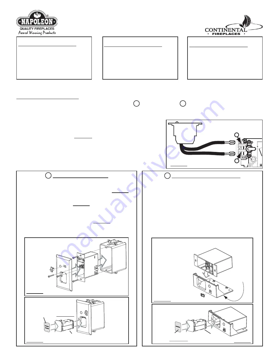
1. RECEIVER INSTALLATION
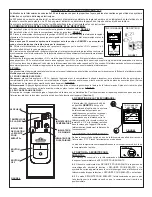
The receiver (W660-0076) can be installed as either a wall mount
A
or a appliance mount
B
. Depending on your application, follow the
applicable steps below after having completed step
1.1
.
Turn off the electrical power and the gas supply to the appliance. Make sure the slide switch on the receiver is set to the “OFF“ position.
1.1
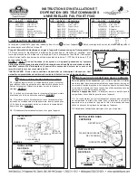
Either disconnect the existing switch wiring at the valve, or connect in parallel*
with any other switch wiring at the valve. For millivolt switch wiring attach the wires
to terminal 1 (marked TPTH) and terminal 3 (marked TH) of the gas valve from the
output terminals on the receiver.
FIGURE 1 Note: If connecting the receiver to an
appliance with electronic ignition, connect the receiver wires to the two leads
from the control module, identifi ed as switch wires. (It may be necessary to
remove the spade connectors and join the wires using wire connectors)
*INSTALLER: It may be advisable to connect a backup switch. This will allow the
homeowner to continue to control the burner in the event of battery failure.
A RECEIVER WALL MOUNT
1.2
Press the battery compartment slightly into the receiver and
release enabling the battery compartment to pop out. Pull off the slide
switch. Slide the receiver out of the wall mounting plate.
FIGURE 2
1.3
Using the screws provided secure the receiver and the wall face
plate to an existing junction box.
FIGURE 2
1.4
Replace the black slide switch with the white one included to match
the cover plate. Place 4 AA batteries into the battery compartment and
slide the compartment back into the receiver.
FIGURE 3
1.5
Turn on the electrical power and the gas supply to the appliance.
F40, F50 AND F50D UNIVERSAL REMOTE
INSTALLATION AND OPERATION
INSTRUCTIONS
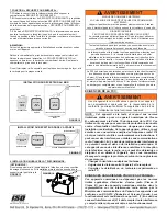
B
RECEIVER APPLIANCE MOUNT
For stove and insert models:
Do not install the receiver in the gas control
valve compartment in some models as this area becomes too hot. On
stoves, it may be installed in or behind the pedestal; on inserts, it may be
installed behind the fl ashings or a similar convenient location.
In a zero clearance model:
The receiver may be installed in the gas control
compartment located below the fi rebox.
1.2
Ensuring that the mounting location will allow for the battery
compartment to pop out, secure the receiver to an appropriate location
depending on the appliance model using the adhesive pad located on the
bottom of the appliance mounting plate.
1.3
Turn on the electrical power and the gas supply to the appliance.
P I P PLOLLTOO
GAS VALVE
TP
TH
TP
TH
RECEIVER
1
3
FIGURE 1
FIREPL
ACE REM
OTE
OFF
ON
REMOTE
BAT.L
OW
JUNCTION
BOX
RECEIVER
SLIDE
SWITCH
WALL FACEPLATE
WALL MOUNT
INSTALLATION
FIREPLA
CE REMO
TE
OFF
ON
REMOTE
BAT.LOW
BATTERY
COMPARTMENT
BATTERY
INSTALLATION
STICKER
(See 7. FINISHING)
FIGURE 2
FIGURE 3
BAT.LO
W
OFF
REMO
TE
ON
APPLIANCE
MOUNTING PLATE
RECEIVER
SLIDE
SWITCH
APPLIANCE MOUNT
INSTALLATION
ADHESIVE
PAD
BATTERY
INSTALLATION
BAT.
LOW
OFF
REMO
TE
ON
BATTERY
COMPARTMENT
STICKER
(See 7. FINISHING)
FIGURE 4
FIGURE 5
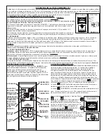
QTY.
PART#
DESCRIPTION
1
W660-0066
Transmitter
2
N043-0002
“AAA”
Batteries
1
W080-0930
Wall Mount Cradle
1
W660-0076
Receiver
1
W500-0405
Wall
Faceplate
1
W500-0404
Fireplace Mounting Plate
1
W660-0080
Slide
Switch
4
W043-0002
“AA”
Batteries
Included with the F40 Universal Remote:
Included with the F50 Universal Remote:
QTY.
PART#
DESCRIPTION
1
W660-0067
Transmitter
2
N043-0002
“AAA”
Batteries
1
W080-0930
Wall Mount Cradle
1
W660-0076
Receiver
1
W500-0405
Wall
Faceplate
1
W500-0404
Fireplace Mounting Plate
1
W660-0080
Slide
Switch
4
W043-0002
“AA”
Batteries
Included with the F50D Universal Remote:
QTY.
PART#
DESCRIPTION
1
**
W660-0087 Transmitter
2
N043-0002
“AAA”
Batteries
1
**
W080-1050 Wall Mount Cradle
1
W660-0076
Receiver
1
W500-0405
Wall
Faceplate
1
W500-0404
Fireplace Mounting Plate
1
W660-0080
Slide
Switch
4
W043-0002
“AA”
Batteries
**
FOR OTHER AVAILABLE COLOURS, ADD THESE LETTERS TO THE BASE PART NUMBER: COLOUR LETTER
BLACK
K
GREY Y
RED
R


