


W415-3006 / A / 05.27.21
EN
42
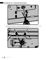
troubleshooting
!
WARNING
• Always light the pilot whether for the fi rst time or if the gas supply has run out, with the glass door (where
applicable) open or removed.
• Turn off gas and electrical power before servicing the appliance.
• Appliance may be hot. Do not service until appliance has cooled.
• Do not use abrasive cleaners
27.9
symptom
problem
test solution
Flames are consistently
too large or too small.
Carboning occurs.
Appliance is over-fi red or under-
fi red.
-
Check pressure readings:
Inlet pressure can be checked by turning screw (A) counter-clock-
wise 2 or 3 turns and then placing pressure gauge tubing over the
test point. Gauge should read as described on the chart below.
Check that main burner is operating on ‘HI’. Outlet pressure can be
checked the same as above using screw (B). Gauge should read as
described on the chart below. Check that main burner is operating
on ‘HI’.
After taking pressure readings, be sure to turn screws
clockwise fi rmly to reseal. DO NOT OVER TORQUE.
Leak test with a soap and water solution.
Air shutter improperly adjusted.
-
Return air shutter to factory-set opening.
For propane - improper lighting
procedure.
For natural gas - undersized
supply line.
-
Ensure lighting procedure is followed carefully. The valve must be in
the off position when the tank valve is turned on. Turn tank on slowly
to allow pressure to equalize. See lighting instructions.
-
Pipe must be sized according to installation code.
Burners burn with
yellow fl ame, accom-
panied by the smell of
gas.
Possible spider web or other
debris.
-
Thoroughly clean burner venturi. See “cleaning / maintenance
instruction” section.
Carbon is being
deposited on glass,
logs, rocks, media, or
combustion chamber
surfaces.
Air shutter is blocked.
-
Ensure air shutter opening is free of lint or other obstructions.
Flame is impinging on the glass,
logs, rocks, media or combus-
tion chamber.
-
Ensure the media is positioned correctly in the appliance.
-
Open air shutter to increase the primary air.
-
Check the input rate: check the manifold pressure and orifi ce size as
specifi ed by the rating plate.
White / grey fi lm forms.
Sulphur from fuel is being depos-
ited on glass, logs, or combus-
tion chamber surfaces.
-
Clean the glass with a recommended gas fi replace glass cleaner.
DO
NOT CLEAN GLASS WHEN HOT.
-
If deposits are not cleaned off regularly, the glass may become
permanently marked.
Pilot will not light. Makes
noise with no spark at
pilot burner.
Wiring: short, loose, or damaged
connections
(poor fl ame rectifi cation).
-
Verify the thermocouple/sensor is clean and the wiring is undamaged.
-
Verify the interrupter block is not damaged or too tight. Verify
connections from pilot assembly are tight; also verify the connections
are not grounding out to any metal. (Remember, the fl ame carries the
rectifi cation current, not the gas. If fl ame lifts from pilot hood, the circuit
is broken. A wrong orifi ce or too high of an inlet pressure can cause the
pilot fl ame to lift)*. The sensor rod may need cleaning.
No signal from remote with no
pilot ignition.
-
Reprogram receiver code.
-
Replace receiver.
Poor grounding.
-
Verify the valve and pilot assembly is properly grounded
Improper switch wiring.
-
Troubleshoot the system with the simplest on/off switch.
Dirty, painted, or damaged pilot
and/or dirty sensor rod.
-
Clean sensor rod with a green Scotch-Brite™ pad to remove any
contamination that may have accumulated. Verify continuity with
multimeter with ohms set at the lowest range.
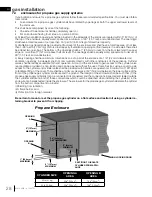
INSERT
PHOTO
OF VALVE
HERE
*Maximum inlet pressure not to exceed 13” w.c.
Pressure
Natural Gas
(inches)
Natural Gas
(millibars)
Propane
(inches)
Propane
(millibars)
Inlet
*7”
(minimum 4.5”)
17.4mb
(minimum 11.2mb)
13”
(minimum 11”)
32.4mb
(minimum 27.4mb)
Outlet
3.5”
8.7mb
10”
24.9mb
symptom
problem
test solution
Pilot sparks but will not
light.
Gas supply.
-
Verify that the incoming gas line ball valve is “open”.
-
Verify that the inlet pressure reading is within acceptable limits, inlet
pressures must not exceed 13” W.C.
Out of propane gas.
-
Fill the tank.
Pilot supply line may contain air.
-
Repeat ignition process several times or purge the pilot supply line.
Incorrect wiring / grounding.
-
Ensure correct polarity of wiring of thermocouple (if equipped).
-
Verify pilot assembly/valve are properly grounded.
Receiver (if equipped).
-
Reset program: hold reset button on receiver and wait for 2 beeps.
Release after second beep. Press small fl ame button on remote
within 20 seconds, you will hear an additional beep (this signals a
successful reset).
-
Replace receiver.
Valve.
-
Check valve and replace if necessary (Do not to overtighten
thermocouple).
Burner continues to
spark and pilot lights
but main burner does
not light.
Short or loose connection in
sensor rod.
-
Verify all connections. Verify the connections from the pilot assembly
are tight. Also, verify these connections are not grounding out to any
metal.
Dirty, painted, or damaged pilot
assembly components.
-
Clean using a green Scotch-Brite™ pad to remove any
contamination that may have accumulated on the sensor rod, pilot
hood, ignitor, or fl ame sensor. Verify continuity with multimeter with
ohms set at the lowest range.
Remote and / or
receiver is not
functioning properly (if
applicable).
Receiver or remote has low
battery.
-
Replace batteries.
Appliance functions but does not
respond to receiver / remote.
-
Ensure appliance is being operated by the same device that turned
it on. Remote controls function if appliance has turned on by remote.
Receiver controls function if appliance was burned on by receiver.
Error with synchronizing.
-
Reset receiver and remote.
Remote too far away from receiver.
-
Refer to “wiring diagram” section.
Wire connector pins are bent.
-
Straighten pins.
Valve wiring is damaged.
-
Replace valve harness.
Appliance won't
perform any
functions
No power to the system.
- Check breaker to verify it is in the "on" position.
- Ensure module is wired to power correctly.
Receiver switch in wrong
position (if equipped).
- Verify that the 3-position switch on the receiver is in the
remote position (middle).
On/off switch in wrong posi-
tion.
- Verify that the switch is in the "on" position.
Transmitter isn't operational
(if required).
- Check battery power and battery orientation.
Light won't function
(if applicable).
Light bulb burnt out.
- Change the bulb.
Light harness damaged.
- Replace the harness.
Switch in wrong position.
- Ensure switch is in "on" position.
No power to lights.
- Ensure power transformer is plugged into junction box and
lights are wired correctly.
If back up batteries are installed, they must also be removed to
re-program
note:


