18
WS-415-090 / 04.03.00
ADJUSTMENTS
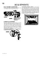
PILOT BURNER ADJUSTMENT
Adjust the pilot screw to provide properly sized flame. Turn
in a clockwise direction to reduce the gas flow.
FLAME MUST ENVELOP
UPPER 3/8" TO 1/2" OF
THERMOCOUPLE &
THERMOPILE
PILOT
THERMOPILE
BURNER
ELECTRODE
THERMO-
COUPLE
FIGURE 43
P
I
PI
PILOT SCREW
LOT
N
O
L
O
T
H I
LO
FF
O
FIGURE 42
FIGURE 44
FIGURE 45
RESTRICTOR
BAFFLE PLATE
PLATE
VENTURI ADJUSTMENT
Natural gas models have air shutters set at 1/16 (.063)
inch open. Propane gas models have air shutters set at ¼
(.250) inch open. Closing the air shutter will cause a more
yellow flame, but can lead to carboning. Opening the air
shutter will cause a more blue flame, but can cause flame
lifting from the burner ports. The flame may not appear
yellow immediately; allow 15 to 30 minutes for the final
flame colour to be established.
AIR SHUTTER ADJUSTMENT MUST ONLY BE DONE BY A
QUALIFIED GAS INSTALLER!
RESTRICTING VERTICAL VENTS:
Vertical installa-
tions running longer than 10 feet may display a very active
flame. If this appearance is not desirable, remove the baffle
plate from the rear wall of the firebox, exposing the flue gas
outlet opening. Bend the restrictor plate up into the flue
opening. Replace the baffle plate. This reduces the velocity
of the exhaust gases, slowing down the flame pattern and
creating a more traditional gentle appearance. Specific in-
structions are shown in "Trouble Shooting".
Summary of Contents for GD27 - N
Page 23: ...23 WS 415 090 04 03 00 NOTES...


