

12
WS-415-63 / 11.24.98
OPERATION / MAINTENANCE
OPERA
OPERA
OPERA
OPERA
OPERATING INSTRUCTIONS
TING INSTRUCTIONS
TING INSTRUCTIONS
TING INSTRUCTIONS
TING INSTRUCTIONS
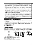
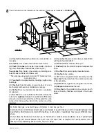
The on-off switch is located on the back of the unit at the top left corner. When lit for the first time, the fireplace will
emit a slight odour for a few hours. This is a normal temporary condition caused by the curing of the logs and the
"burn-in" of internal paints and lubricants used in the manufacturing process and will not occur again. Simply
open a window to sufficiently ventilate the room. After extended periods of non-operation such as following a
vacation or a warm weather season, the fireplace may emit a slight odour for a few hours. This is caused by dust
particles in the heat exchanger burning off. Open a window to sufficiently ventilate the room.
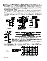
INSTRUCTIONS TO TURN OFF GAS:
1.
Turn off all electrical power to the unit if service is to
be performed.
2.
Push in gas control knob slightly and turn clockwise
to off. DO NOT FORCE.
When lighting and re-lighting, the gas knob cannot
be turned from pilot to off unless the knob is
depressed slightly.
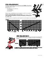
1.
Stop! Read the above safety information
on this label.
2.
Turn off all electric power to the fireplace.
3.
Turn the gas knob clockwise
to off.
4.
Wait five (5) minutes to clear out any gas. If you
smell gas including near the floor. Stop! Follow "B"
in the above safety information on this label. If you
don't smell gas go the next step.
5.
Turn gas knob counter-clockwise
to pilot.
6.
Depress slightly and hold gas knob while lighting the pilot
with the push button ignitor. Keep knob depressed for one
minute, then release. If pilot does not con-
tinue to burn, repeat steps 3 through 5.
7.
With pilot lit, depress and turn gas knob
counter-clockwise
to on.
8.
If equipped with remote on-off switch/thermostat,
main burner may not come on when you turn valve to on. Re-
mote switch must be in the on position to ignite burner.
9.
Turn on all electric power to the fireplace.
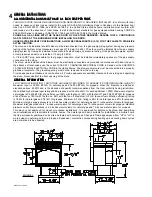
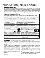
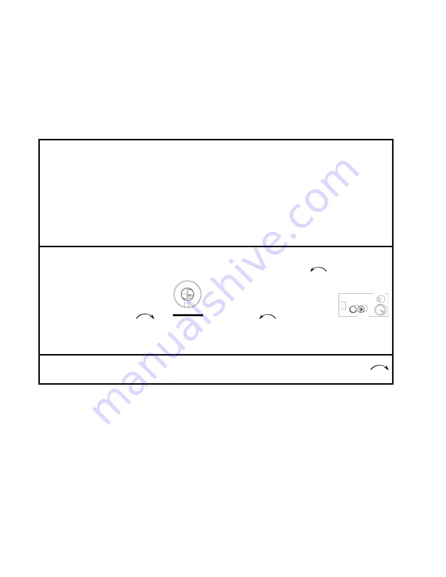
P
I
N
O
L
O
T
FF
O
GAS KNOB
LO
FLAME
KNOB
ADJUSTMENT
I H
VARIABLE
SPEED
SWITCH
L
P
O
FF
N
T
I
O
O
PILOT
KNOB
ON/OFF
IGNITOR
PIEZO
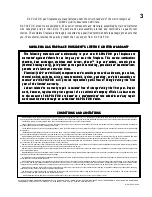
LIGHTING INSTRUCTIONS:
WARNING
The gas valve has an interlock device which will not allow the pilot burner to be
lit until the thermocouple has cooled. Allow approximately 60 seconds for the thermocouple to cool.
• Do not touch any electric switch; do not use any phone in your building.
• Immediately call your gas supplier from a neighbour's phone.
Follow the gas supplier's instructions.
• If you cannot reach your gas supplier, call the fire department.
FOR YOUR SAFETY READ BEFORE OPERATING
A.
This fireplace is equipped with a pilot which must be lit by hand while following these instructions exactly.
B.
Before operating smell all around the fireplace area for gas and next to the floor because some gas is heavier than
air and will settle on the floor.
C.
Use only your hand to turn the gas control knob. Never use tools. If the knob will not turn by hand, do not try to
repair it. Call a qualified service technician. Force or attempted repair may result in a fire or explosion.
D.
Do not use this fireplace if any part has been under water. Immediately call a qualified service technician to inspect
the fireplace and replace any part of the control system and any gas control which has been under water.
WHAT TO DO IF YOU SMELL GAS:
• Turn off all gas to the fireplace.
• Open windows.
• Do not try to light any appliance.
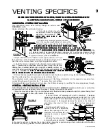
1.
In order to properly clean the burner and pilot as-
sembly, remove the logs to expose both assemblies.
2.
Keep the control compartment, logs, burner, air
shutter opening and the area surrounding the logs
clean by vacuuming or brushing,
at least once a year
.
3.
Check to see that all burner ports are burning.
Clean out any of the ports which may not be burning
or are not burning properly. (end brick panel must be
removed in order to facilitate burner removal, where
applicable.)
4.
Check to see that the pilot flame is large enough to engulf
the thermocouple and thermopile and reaches toward the burner
with the third jet.
5.
Replace the cleaned logs.
6.
Check to see that the main and runner burners ignite com-
pletely on all openings when the gas knob for the burners is
turned on. A 5 to 10 second total light-up period is satisfactory.
If ignition takes longer, consult your Napoleon dealer / distribu-
tor.
7.
Check that the gasketing on the sides, top and bottom of the
door is not broken or missing. Replace if necessary.
MAINTENANCE
MAINTENANCE
MAINTENANCE
MAINTENANCE
MAINTENANCE
TURN OFF THE GAS AND ELECTRICAL POWER BEFORE SERVICING THE FIREPLACE.
CAUTION: Label all wires prior to disconnection when servicing controls. Wiring errors can cause improper and danger-
ous operation. Verify proper operation after servicing. This fireplace and its venting system should be inspected before
use and at least annually by a qualified service person. The fireplace area must be kept clear and free of combustible
materials, gasoline or other flammable vapours and liquids. The flow of combustion and ventilation air must not be
obstructed.


