

13
WS-415-63 / 11.24.98
ADJUSTMENTS
PILOT BURNER ADJUSTMENT
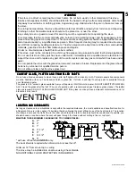
PILOT BURNER ADJUSTMENT
PILOT BURNER ADJUSTMENT
PILOT BURNER ADJUSTMENT
PILOT BURNER ADJUSTMENT
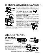
Adjust the pilot screw to provide properly
sized flame. Turn in a clockwise direc-
tion to reduce the gas flow.
FIGURES 26 & 27.
VENTURI ADJUSTMENT
VENTURI ADJUSTMENT
VENTURI ADJUSTMENT
VENTURI ADJUSTMENT
VENTURI ADJUSTMENT
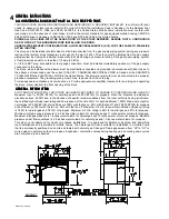
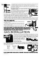
To access the venturi, remove the four screws securing the burner to the
base; slide to the left, lift up and out. Natural gas models have air shut-
ters set at 3/16 (.188) inch open. Propane gas models have air shutters
set at 1/4 (.250) inch open. Closing the air shutter will cause a more
yellow flame, but can lead to carboning. Opening the air shutter will cause
a more blue flame, but can cause flame lifting from the the burner ports.
The flame may not appear yellow immediately; allow 15 to 30 minutes for
the final flame colour to be established.
P
I
PI
PILOT SCREW
LOT
N
O
L
O
T
H I
LO
FF
O
FIGURE 26
FLAME MUST ENVELOP
UPPER 3/8" TO 1/2" OF
THERMOCOUPLE &
THERMOPILE
THERMOPILE
THERMO-
COUPLE
FIGURE 27
FIGURE 28
Air shutter adjustment must only be done by a qualified gas installer!
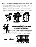
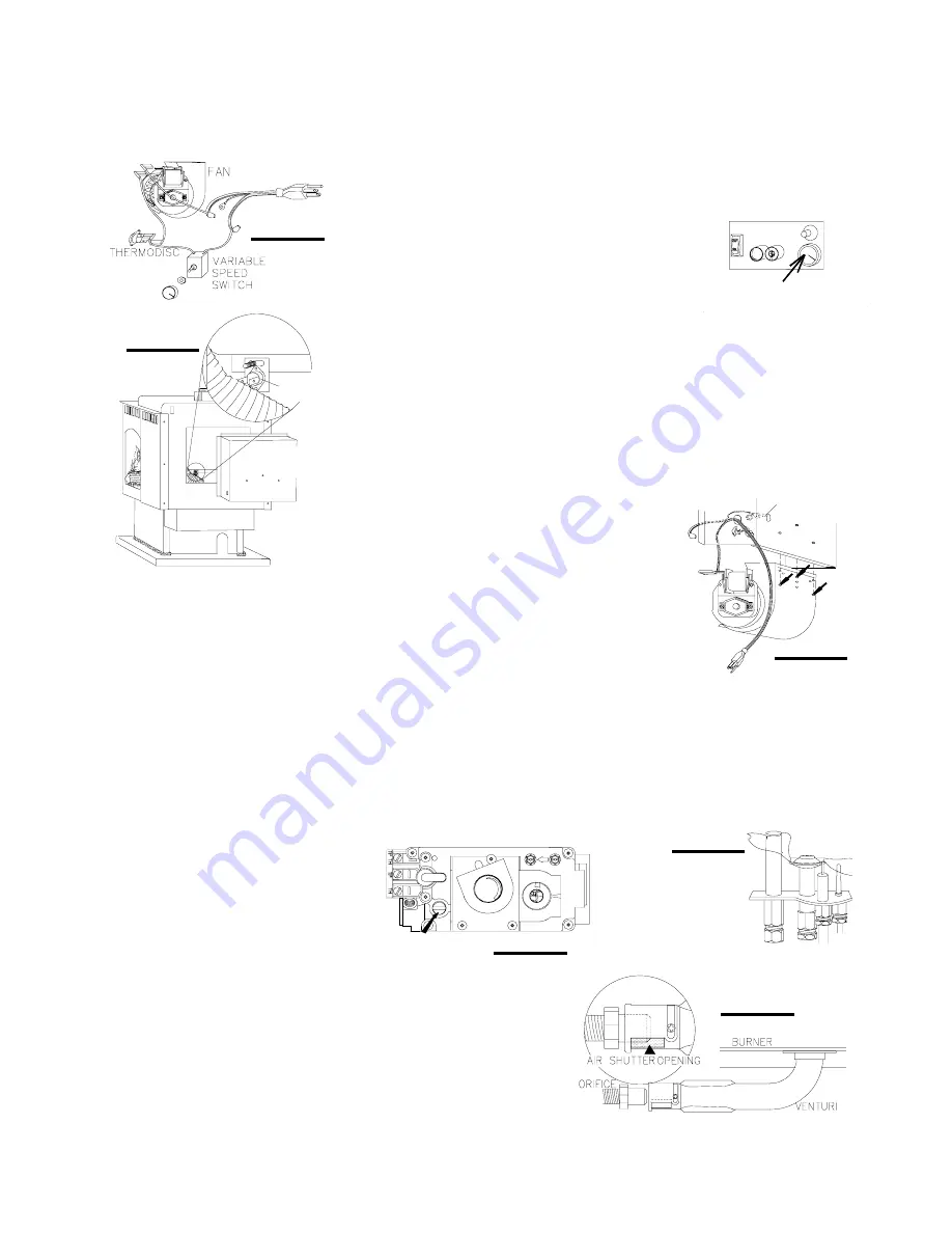
OPTIONAL BLOWER INSTALLATION
Provision has been made on the Napoleon stove to install an optional blower on
the rear wall. Because the blower is thermally activated, when turned on, it will
automatically start after approximately 30 minutes from a cold start (pilot off) or
15 minutes from a warm start (pilot on) and will run for approximately 30 minutes
after the stove has been turned off. Use of the fan in-
creases the output of heat.
1.
Mount the variable speed switch: insert the rheostat
stem through the 3/8" diameter hole in the pedestal
and from the front secure with the pal nut. Add the knob.
2.
Remove the blower housing located at the rear of the
stove. Attach the bracket holding the heat sensor as shown to the weld stud and
secure using one of the #6 nuts.
FIGURE 24.
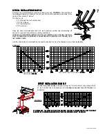
3.
Attach the bare end of the wire (with one bare lead / one flag connector end) to
the
black
wire of the speed switch using a nut connector. Attach the flag connec-
tor at the other end to one of the prongs of the heat sensor.
4.
Thread the leads of the power cord through the slot located at the bottom left
of the blower housing. Attach the terminal of the ground wire
(green)
to the
threaded weld stud and secure with a nut.
5.
Connect one of the two bare leads of the other wire to the
white
wire of the
speed switch using a nut connector. Connect the other end to the bare lead wire
of the blower cord using a nut connector.
6.
Attach the other terminal of the wire
(already at-
tached to the blower)
to the heat sensor.
7.
Mount the cord terminal to the other blower prong.
8.
Using the holes shown, attach the blower to the
blower housing.
9.
Bring out any slack in the blower cord. Place the cord into the split strain relief bushing,
just at the point where the cord enters the slot. Clamp the two pieces together and insert
the bushing securely into the slot.
FIGURE 25.
VARIABLE SPEED
SWITCH
H
I
L
P
O
FF
N
T
I
O
O
LO
GROUND
WELD STUD
FIGURE 25
white
black
ground
FIGURE 23
SENSOR
BLOWER
HOUSING
HEAT
FIGURE 24


