
7
WS-415-63 / 11.24.98
SPECIAL INST
SPECIAL INST
SPECIAL INST
SPECIAL INST
SPECIAL INSTALLA
ALLA
ALLA
ALLA
ALLATION EXAMPLE
TION EXAMPLE
TION EXAMPLE
TION EXAMPLE
TION EXAMPLE
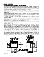
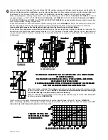
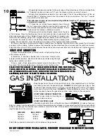
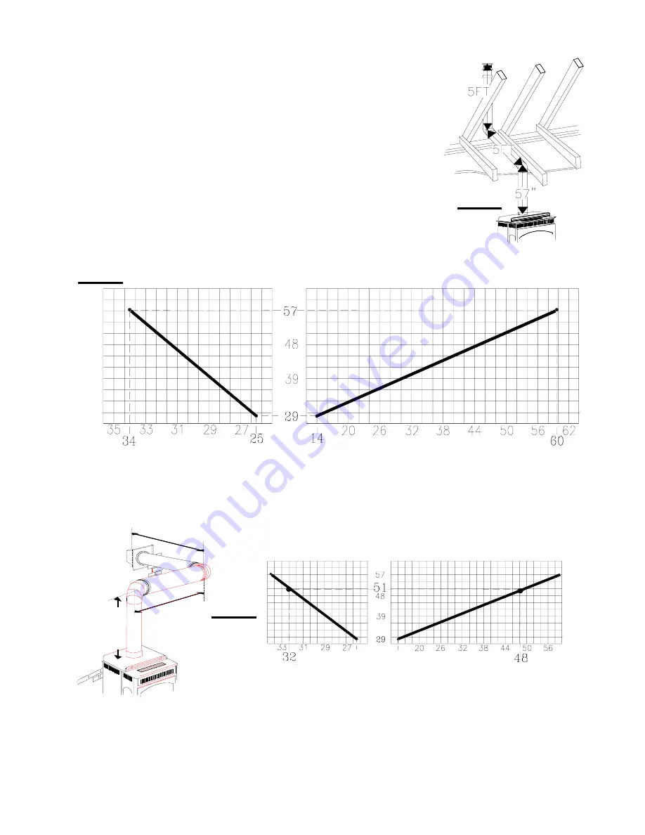
A through the roof installation requires a total 5 foot rise.
FIGURE 6.
The location of
the fireplace dictates a horizontal run of 5 feet. What is the required vertical rise to the
centre of the initial 90° elbow?
The total run is:
5 ft. (through the roof vertical rise)
10 ft. (90° elbow)
5 ft. (horizontal run)
20 ft. (total run)
Using the chart, will determine that a 57 inch minimum vertical rise immediately off
the unit is required for satisfactory venting conditions.
ALTHOUGH THE IMMEDIATE VERTICAL RUN MAY BE GREATER THAN 57 INCHES, THE MAXI-
MUM COMBINATION OF HORIZONTAL AND VERTICAL RUNS, BEYOND THE 57 INCHES,
MUST
NOT EXCEED 20 FEET.
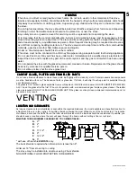
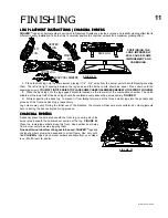
Use the chart below to calculate the required horizontal run from the fireplace in an offset installation.
FIGURE 6
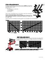
FIGURE 7
OFFSET INST
OFFSET INST
OFFSET INST
OFFSET INST
OFFSET INSTALLA
ALLA
ALLA
ALLA
ALLATION EXAMPLE
TION EXAMPLE
TION EXAMPLE
TION EXAMPLE
TION EXAMPLE
If a
first run of 48 inches
is required, using the "First Vent Run" chart shows that a
51 inch vertical rise is necessary and a
maximum second run of 32 inches
is
allowable.
IF NECESSAR
IF NECESSAR
IF NECESSAR
IF NECESSAR
IF NECESSARYYYYY, THE FIRST RUN AND THE SECOND RUN MA
, THE FIRST RUN AND THE SECOND RUN MA
, THE FIRST RUN AND THE SECOND RUN MA
, THE FIRST RUN AND THE SECOND RUN MA
, THE FIRST RUN AND THE SECOND RUN MAY BE REVERSED SO THA
Y BE REVERSED SO THA
Y BE REVERSED SO THA
Y BE REVERSED SO THA
Y BE REVERSED SO THAT THE FIRST
T THE FIRST
T THE FIRST
T THE FIRST
T THE FIRST
RUN MA
RUN MA
RUN MA
RUN MA
RUN MAY BE A MAXIMUM LENGTH OF 34" AND THE SECOND RUN 60" MAXIMUM.
Y BE A MAXIMUM LENGTH OF 34" AND THE SECOND RUN 60" MAXIMUM.
Y BE A MAXIMUM LENGTH OF 34" AND THE SECOND RUN 60" MAXIMUM.
Y BE A MAXIMUM LENGTH OF 34" AND THE SECOND RUN 60" MAXIMUM.
Y BE A MAXIMUM LENGTH OF 34" AND THE SECOND RUN 60" MAXIMUM.
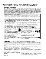
14" MIN
60" MAX
57"
MAX
29"
MIN
second run
first run
25" MIN
34" MAX
FIGURE 8
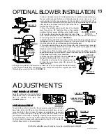
CALCULATED
SECOND
VENT RUN IN INCHES
INCHES
INCHES
INCHES
INCHES
CALCULATED
FIRST VENT RUN IN INCHES
INCHES
INCHES
INCHES
INCHES


