

9
WS-415-63 / 11.24.98
VENTING SPECIFICS
FOR SAFE AND PROPER OPERA
FOR SAFE AND PROPER OPERA
FOR SAFE AND PROPER OPERA
FOR SAFE AND PROPER OPERA
FOR SAFE AND PROPER OPERATION OF THE STOVE, FOLLOW THE VENTING INSTRUCTIONS EXACTL
TION OF THE STOVE, FOLLOW THE VENTING INSTRUCTIONS EXACTL
TION OF THE STOVE, FOLLOW THE VENTING INSTRUCTIONS EXACTL
TION OF THE STOVE, FOLLOW THE VENTING INSTRUCTIONS EXACTL
TION OF THE STOVE, FOLLOW THE VENTING INSTRUCTIONS EXACTLY
YY
YY.....
ALL HORIZONT
ALL HORIZONT
ALL HORIZONT
ALL HORIZONT
ALL HORIZONTAL RUNS MUST HA
AL RUNS MUST HA
AL RUNS MUST HA
AL RUNS MUST HA
AL RUNS MUST HAVE A MINIMUM
VE A MINIMUM
VE A MINIMUM
VE A MINIMUM
VE A MINIMUM 1 INCH
1 INCH
1 INCH
1 INCH
1 INCH RISE PER FOOT
RISE PER FOOT
RISE PER FOOT
RISE PER FOOT
RISE PER FOOT.....
HORIZONT
HORIZONT
HORIZONT
HORIZONT
HORIZONTAL VENTING INST
AL VENTING INST
AL VENTING INST
AL VENTING INST
AL VENTING INSTALLA
ALLA
ALLA
ALLA
ALLATION
TION
TION
TION
TION
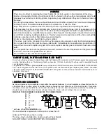
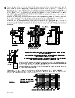
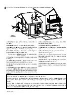
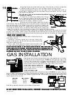
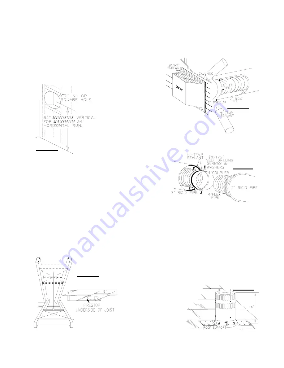
This application occurs when venting through an exterior wall.
FIGURES 2, 3, & 10
.
Having determined the air terminal location:
1.
Cut or frame a hole in the exte-
rior wall with a round or a square
opening of a minimum 9".
THE
THE
THE
THE
THE
STOVE PIPE MUST RISE 1" PER
STOVE PIPE MUST RISE 1" PER
STOVE PIPE MUST RISE 1" PER
STOVE PIPE MUST RISE 1" PER
STOVE PIPE MUST RISE 1" PER
FOOT OF RUN.
FOOT OF RUN.
FOOT OF RUN.
FOOT OF RUN.
FOOT OF RUN.
2.
Stretch the 4" diameter aluminum flexible
liner to the required length taking into account the
additional length needed for the finished wall surface.
SP
SP
SP
SP
SPACERS ARE A
ACERS ARE A
ACERS ARE A
ACERS ARE A
ACERS ARE ATT
TT
TT
TT
TTACHED TO THE 4" INNER FLEX LINER
ACHED TO THE 4" INNER FLEX LINER
ACHED TO THE 4" INNER FLEX LINER
ACHED TO THE 4" INNER FLEX LINER
ACHED TO THE 4" INNER FLEX LINER
AAAAAT PREDETERMINED INTERV
T PREDETERMINED INTERV
T PREDETERMINED INTERV
T PREDETERMINED INTERV
T PREDETERMINED INTERVALS TO MAINT
ALS TO MAINT
ALS TO MAINT
ALS TO MAINT
ALS TO MAINTAIN A 1-1/4" AIR
AIN A 1-1/4" AIR
AIN A 1-1/4" AIR
AIN A 1-1/4" AIR
AIN A 1-1/4" AIR
GAP TO THE 7" OUTER STOVE PIPE. THESE SPACERS MUST NOT BE REMOVED.
GAP TO THE 7" OUTER STOVE PIPE. THESE SPACERS MUST NOT BE REMOVED.
GAP TO THE 7" OUTER STOVE PIPE. THESE SPACERS MUST NOT BE REMOVED.
GAP TO THE 7" OUTER STOVE PIPE. THESE SPACERS MUST NOT BE REMOVED.
GAP TO THE 7" OUTER STOVE PIPE. THESE SPACERS MUST NOT BE REMOVED.
Slip
a 4" diameter length of aluminum flexible liner a minimum of 2" over the inner sleeve of the air
terminal. Secure to the sleeve using 3 screws. Seal the joint and screw heads using the high
temperature sealant provided.
FIGURE 12.
3.
Slip the first section of 7" diameter stove pipe a minimum of 2" over
the outer sleeve of the air terminal
.
Secure to the sleeve using 3 screws.
Seal the joint and screw heads using high temperature sealant.
4.
Install the firestop / wall plate to the finished interior wall, maintain-
ing a 1" clearance to combustibles.
Insert the liners through the firestop.
Holding the air terminal (lettering in an upright, readable position), se-
cure to the exterior wall. Make weather tight by sealing with caulking (not
supplied).
FIGURE 10
.
THE AIR TERMINAL MOUNTING PLA
THE AIR TERMINAL MOUNTING PLA
THE AIR TERMINAL MOUNTING PLA
THE AIR TERMINAL MOUNTING PLA
THE AIR TERMINAL MOUNTING PLATE MUST
TE MUST
TE MUST
TE MUST
TE MUST
NOT BE RECESSED INTO THE EXTERIOR WALL OR SIDING.
NOT BE RECESSED INTO THE EXTERIOR WALL OR SIDING.
NOT BE RECESSED INTO THE EXTERIOR WALL OR SIDING.
NOT BE RECESSED INTO THE EXTERIOR WALL OR SIDING.
NOT BE RECESSED INTO THE EXTERIOR WALL OR SIDING.
5.
If more than one length of liner needs to be used to reach the stove, couple them together as illustrated in
Figure 12
.
Seal the joints using the same procedure as described in Item 3.
The vent system must be supported approximately every 10 feet along a horizontal run. Use supports or equivalent non-
combustible strapping to maintain the 1" clearance from combustibles.
A firestop/wall plate must be placed on the inside of each framed opening in a wall that the stove pipe passes through.
VER
VER
VER
VER
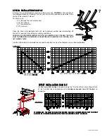
VERTICAL VENTING INST
TICAL VENTING INST
TICAL VENTING INST
TICAL VENTING INST
TICAL VENTING INSTALLA
ALLA
ALLA
ALLA
ALLATION
TION
TION
TION
TION
THIS APPLICATION OCCURS WHEN VENTING THROUGH A ROOF
FIGURE 4
. Installation kits for various roof pitches
are available from your Napoleon dealer. See page 5 to order the specific kit required.
1.
Move the stove into position. Try to center the exhaust of the stove midway between two joists to prevent having to cut
them. Use a plumb bob to line up the center of the opening.
2.
Cut and frame a 9" opening in the roof to provide a 1" clearance
between the stove pipe and any combustible material. DO NOT FILL THIS
SPACE WITH ANY TYPE OF MATERIAL. Nail headers between the joists
for extra support. A firestop/wall plate must be placed on the bottom of
each framed opening in a floor or ceiling that the stove pipe passes
through.
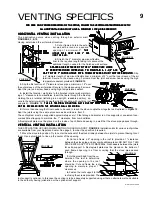
3.
Hold a plumb bob from the un-
derside of the roof to determine
where the opening in the roof
should be. Cut and frame the roof
opening to maintain proper 1"
clearances.
4.
Fasten the roof support to the
roof using the screws provided. The
roof support is optional. In this case the venting is to be adequately supported using either an alternate method suitable
to the authority having jurisdiction or the optional roof support.
FIGURE 11
FIGURE 12
FIGURE 13
FIGURE 10
FIGURE 14


