EN
W415-1426 / D / 05.22.19
7
general information
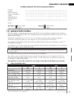
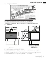
1.4
rating plate information
This illustration is for reference only. Refer to the rating plate on the appliance for accurate information.
Certified to Canadian and American National Standards:
CSA 2.22-2016 / ANSI Z21.50-2016 for Vented Decorative Gas Appliances
Certifié selon les normes Nationales Canadiennes et Américaines:
CSA 2.22-2016 / ANSI Z21.50-2016 pour les Appareils à gaz décoratif à évacuation
Direct vent, vented gas fireplace. Approved for bedroom, bathroom and bed-sitting room installation. Suitable for mobile home installation, if installed in accordance with the current
standard CAN / CSA Z240MH Series gas equipped mobile homes in Canada, or, in the United States, the
Manufactured Home Construction and Safety Standard, Title 24 CFR, Part
3280
. When this US Standard is not applicable, use the
Standard for Fire Safety Criteria for Manufactured Home Installations, Sites and Communities
, ANSI / NFPA 501A. This appliance
must be installed in accordance with local codes, if any; if none, follow the current ANSI Z223.1 or CSA B149.
For use with barrier W565-0195. Follow installation instructions.
Foyer à gaz ventilé. Homologué pour installation dans une chambre à coucher, une salle de bain et un studio. Approprié pour installation dans une maison mobile si son installation
conforme aux exigences de la norme CAN / CSA Z240MH Séries de maisons mobile équipées au gaz en vigueur au Canada, ou, aux États-Unis selon la norme
24 CFR, Part 3280,
Manufactured Home Construction and Safety Standard
. Dans le cas ou cette norme d’États-Unis n’est pas pertinentes, utiliser la norme
NFPA 501A, Fire Safety Criteria for Manufactured
Home Installations, Sites and Communities
. Installer l’appareil selon les codes ou règlements locaux ou, en l’absence de tels règlements, selon les codes d’installation ANSI Z223.1 ou
CSA B149 en vigueur.
Utilisez uniquement avec l’écran W565-0195. Suivre les instructions d’installation.
9700539 (WSL)
4001658 (NAC)
4001657 (NGZ)
4001659 (WUSA)
WOLF STEEL LTD.
24 Napoleon Road, Barrie, ON, L4M 0G8 Canada
Manifold Pressure:
3.5” w.c. (NG)
Minimum Supply Pressure:
4.5” w.c. (NG)
Maximum Supply Pressure:
7”** w.c. (NG)
Pression au Collecteur:
3,5” d’une colonne d’eau (GN)
Pression d’Alimentation Min.:
Pression d’Alimentation Max.:
**Maximum inlet pressure not to exceed 13”.
Manifold Pressure:
10” w.c. (P)
Minimum Supply Pressure:
11” w.c. (P)
Maximum Supply Pressure:
13” w.c. (P)
Pression au Collecteur:
10” d’une colonne d’eau (P)
Pression d’Alimentation Min.:
11” d’une colonne d’eau (P)
Pression d’Alimentation Max.:
13” d’une colonne d’eau (P)
**Pression d’alimentation maximale ne devait pas dépasser 13”.
Minimum clearance to combustible materials: / Dégagements minimaux des matériaux combustibles:
Minimum and maximum horizontal vent lengths are 25” and 20’
respectively.
Les longeurs horizontales minimale et maximale sont 25 pounces
et 20 pieds respectivement.
This appliance must be installed using an adapter kit GS-150KT.
Cet appareil doit être installé en utilisant un ensemble adaptateur
GS-150KT.
Insert test-
ing agency
logo
Serial Number / N° de Série:
W385-1998 / C
GDS28
WARNING
:
Do not add any material to the appliance which will come in contact with the
flames, other than that supplied by the manufacturer with the appliance.
AVERTISSEMENT
:
N’ajoutez pas à cet appareil aucun matériau devant entretien
contact avec les flammes autre que celui qui est fourni avec cet appareil par le fabricant.
The appliance must be vented using the appropriate Napoleon vent kits. See installation
manual for venting specifications. Proper reinstallation and resealing is necessary after servicing
the vent-air intake system.
L’appareil doit être ventilé à l’aide de l’ensemble d’évacuation propre à Napoleon. Référez au
manuel d’installation pour les spécifications d’évacuation. Il est nécessaire de bien réinstaller et
resceller l’évacuation après avoir executer l’entretien du système de prise d’air.
Electrical rating: 115V, 60HZ. Less than 12 amperes.
Spécifications électriques: 115V, 60HZ. Moins de 12 ampère.
VENTED DECORATIVE GAS APPLIANCE: NOT A SOURCE OF
HEAT, NOT INTENDED FOR USE AS A HEATING APPLIANCE,
NOT FOR USE WITH SOLID FUEL.
APPAREIL À GAZ DÉCORATIF À ÉVACUATION: N’EST PAS
UNE SOURCE DE CHALEUR; N’EST PAS DESTINÉ À ÈTRE
UTILISÉ COMME UN APPAREIL DE CHAUFFAGE; NE
CONVIENT PAS AUX COMBUSTIBLES SOLIDES.
FOR USE WITH GLASS DOORS CERTIFIED WITH THIS APPLIANCE ONLY.
POUR UTILISATION UNIQUEMENT AVEC LES PORTES EN VERRE
CERTIFIÉES AVEC L’APPAREIL.
Refer to the Intertek Directory of Building Products (https://bpdirectory.intertek.com) for
detailed information.
A
7"
B
2"
C
1"
20” to ceiling from stove top.
20” entre le dessus de l’appareil et le plafond.
GDS28-N
CDVS280-N
GDS28-P
CDVS280-P
DIRECT VENT MODEL / MODÈLE D’ÉVENT DIRECT
Altitude / Élévation
Input / Alimentaion*
Reduce Input / Alimentation Reduite
Output (Model GDS28) / Rendement
Output (Model GS28) / Rendement
P4
GS28-N
CS280-N
GS28-P
CS280-P
“B” VENT MODEL / MODÈLE D’ÉVENT « B »
D
17 1/2"
E
6 1/4"
F
9 1/2"
0-4,500ft (0-1370m)
30,000 BTU/hr
18,000 BTU/hr
25,500 BTU/hr
24,600 BTU/hr
63.6%
0-4,500ft (0-1370m)
26,000 BTU/hr
15,000 BTU/hr
22,360 BTU/hr
21,600 BTU/hr
63.2%
* Altitude downrating conditions apply to Canada only.
* Les conditions de baissé d’évaluation selon l’altitude s’appliquent
au Canada seulement.
SAMPLE
SAMPLE
appliance
uctions.
e si son installation
son
orme
me
24 CFR, Part 3280,
24 CFR,
A, Fire Safety Criteria for Manufactured
ty Criteria fo
lon les codes d’installation ANSI Z223.1 ou
es codes d’installation ANS
WOLF
G)
re:
4.5” w.c. (NG)
Pressure:
7”** w.c. (NG)
Collecteur:
Collecteur:
3,5” d’une colonne d’eau (GN)
3,5” d’une colonne d’eau (GN)
on d’Alimentation Min.:
n d’Alimentation Min
Pression d’Alimentation Max.:
sion d’Alimentation Max.
**Maximum inlet pressure not to exceed 13”.
Maximum inlet pressure not to e
Manifold Pressure:
Manifold Pressure:
10” w.c. (P)
10” w.c
Minimum Supply Pressure:
Minimum Supply Pressure:
11” w.c. (P)
11” w.c.
Maximum Supply Pressure:
Maximum Supply Pre
13” w.c. (P)
13” w.c. (P
Pression au Collecteur:
ssion au Collecteur:
10” d’une colonne d’eau (P)
10” d’une colonne d’eau (P
Pression d’Alimentation Min.:
Pression d’Alimentation Min.:
11” d’une colonne d’eau (
11” d’une colonne d’ea
Pression d’Alimentation Max.:
Pression d’Alimentation Max.:
13” d’une colonne
13” d’une
**Pression d’alimentation maximale ne devait pa
**Pression d’alimentation maximale ne devait
Minimum clearance to combustible materials: / Dégagements minimaux des matériaux com
Minimum clearance to combustible materials: / Dégagements minimaux des matériaux co
Minimum and maximum horizon
mum and maximum horiz
respectively.
ctively.
Les longeurs horiz
eurs ho
et 20 pieds
This
LE
LE
LE
E
E
E
E
E
E
LE
LE
E
E
LE
E
E
E
E
E
E
E
E
E
E
E
VENTED DECORATIVE GAS APPLIANCE: NOT A SOURCE OF
VENTED DECORATIVE GAS APPLIANCE: NOT A SOURCE OF
HEAT, NOT INTENDED FOR USE AS A HEATING APPLIANCE
HEAT, NOT INTENDED FOR USE AS A HEATING APPLIANC
NOT FOR USE WITH SOLID FUEL.
NOT FOR USE WITH SOLID
APPAREIL À GAZ DÉCORATIF À ÉVACUATION:
APPAREIL À GAZ DÉCORATIF À ÉVACUATION
UNE SOURCE DE CHALEUR; N’EST PAS
UNE SOURCE DE CHALEUR; N’EST PAS
UTILISÉ COMME UN APPAREIL D
UTILISÉ COMME UN APPAREIL
CONVIENT PAS AUX CO
CONV
FOR USE WITH GLAS
FOR USE
POUR UTILISA
OUR UT
CERTIFIÉ
ERTIF
S
A
A
7"
B
B
2"
C
C
1"
1"
20” to ceiling from stove
20” to ceiling from st
20” entre le dess
20” entre le dess
S280-P
80-P
n
mentaion*
aion*
t / Alimentation Reduite
tion Reduite
t (Model GDS28) / Rendement
Rendement
Output (Model GS28) / Rendement
utput (Model GS28) / Rendement
P4
CS280-P
CS280-P
M
SA
S
SA
S
S
SA
SA
SA
SA
A
A
A
A
A
A
A
A
A
D
D
17 1/2"
17 1
E
E
6 1/4
6 1
F
F
0-4,500ft (0-1370m)
0-4,500ft (0-1370m)
26,000 BTU/hr
26,000 BTU/hr
15,000 BTU/hr
15,000 BTU/hr
22,360 BTU/hr
22,360 B
21,600 BTU/hr
21,600 BT
63.2%
63
note:
The rating plate must remain with the appliance at all times. It must not be removed.
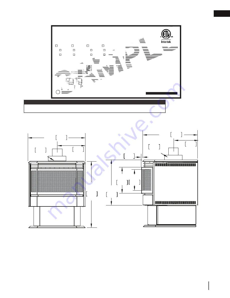
1.5 dimensions
GAS LINE ACCESS HOLE LOCATED
IN PEDESTAL BASE
26 3/4"
680mm
22 1/2" 572mm
11 1/4" 286mm
7" 178mm
Ø AIR INTAKE
10"
254mm
12"
305mm
17 3/4"
451mm
18 1/2" 470mm
5 1/2" 127mm
4" 102mm
Ø FLUE
SAFETY
BARRIER
1 3/4"
44mm
front view
right side view
1.3
mobile home installation (model GDS28)
In Canada, mobile home installation may be vented horizontally or vertically. In the United States, it may only be
installed vertically. See "vertical venting" or "horizontal air terminal installation" sections for installation details.
For mobile home installations, the appliance must be fastened in place. It is recommended that the appliance be
secured in all installations. Use the levelling / securing kit (GDSLL-KT) for this purpose.


