background image

122

W415-1371 / 09.19.14

FR

8

6

7

5

4

3

2

1

8

6

7

5

4

3

2

1

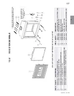
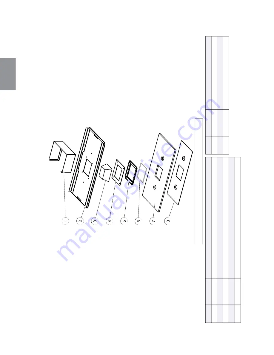
REF

. #

P

ART #

DESCRIPTION

1

W585-0830

PROTECTEUR DE LUMIÈRE DE VEILLE

2

W010-3138

ASSEMBLAGE DE LA

 POR

T

E

3

N402-0001

L'ASSEMBLAGE DE LUMIÈRE

4

W290-0080

PLAQUE DE RECOUVREMENT

 DU JOINT

 D'ÉT

ANCHÉITÉ 

5

W280-0071

PLAQUE DE RECOUVREMENT

 DU LENTILLE

REF

. #

P

ART #

DESCRIPTION

6

W300-0067

VERRE

7

W290-0239

8

W500-0756

RETENUE DU POR

T

E

CES 

AR

TICLES PEUT

 DIFFÉRER DE CELLE ILLUSTRÉ

POR

T

E DE JOINT

 D’ÉT

A

NCHÉITÉ

16.0 

ASSEMBLA

GE DE LA POR

TE

Summary of Contents for HDX52NT-1

Page 1: ...touch any electrical switch do not use any phone in your building Immediately call your gas supplier from a neighbour s phone Follow the gas supplier s instructions If you cannot reach your gas supplier call the fire department Installation and service must be performed by a qualified installer service agency or the supplier This appliance may be installed in an aftermarket permanently located man...

Page 2: ...GING 32 6 3 GLASS DOOR REMOVAL INSTALLATION 33 6 4 BURNER INSTALLATION 34 6 5 LOGO PLACEMENT 34 7 0 ELECTRICAL INFORMATION 35 7 1 HARD WIRING CONNECTION 35 7 2 RECEPTACLE WIRING DIAGRAM 35 7 3 BATTERY HOLDER INSTALLATION 36 7 4 WIRING DIAGRAM 37 8 0 OPERATION 38 8 1 GENERAL TRANSMITTER LAYOUT 38 8 2 INITIALIZING THE TRANSMITTER BATTERY HOLDER FOR THE FIRST TIME 38 8 3 TEMPERATURE DISPLAY 39 8 4 FL...

Page 3: ...MING See the section FRAMING MINIMUM CLEARANCE TO COMBUSTIBLE ENSLOSURES for non combustible materials such as tile marble granite etc IMPORTANT Extra support may be required See the section CONTROL ACCESS for the control box See the section BATTERY HOLDER See the section BURNER INSTALLATION SAFETY BARRIER Batteries must be disposed of according to the local laws and regulations Some batteries may...

Page 4: ...nd at least annually by a qualified service person More frequent cleaning may be required due to excessive lint from carpeting bedding material etc The appliance area must be kept clear and free from combustible materials gasoline and other flammable vapors and liquids Under no circumstances should this appliance be modified This appliance must not be connected to a chimney flue pipe serving a sep...

Page 5: ...or installation in a bedroom or bathroom unless the unit is a direct vent sealed combustion product ALWAYS LIGHT THE PILOT WHETHER FOR THE FIRST TIME OR IF THE GAS SUPPLY HAS RUN OUT WITH THE GLASS DOOR OPENED OR REMOVED PROVIDE ADEQUATE CLEARANCE FOR SERVICING AND OPERATING THE APPLIANCE PROVIDE ADEQUATE VENTILATION NEVER OBSTRUCT THE FRONT OPENING OF THE APPLIANCE OBJECTS PLACED IN FRONT OF THE ...

Page 6: ...he required clearance to combustibles is maintained the most desirable and beneficial location for an appliance is in the center of a building thereby allowing the most efficient use of the heat created The location of windows doors and the traffic flow in the room where the appliance is to be located should be considered If possible you should choose a location where the vent will pass through th...

Page 7: ...ROPRIÉTAIRE POUR LES MATÉRIAUX DE FINITION L EXTENSION HORIZONTALE MAXIMALE 2 RÉFÉRER AU MANUAL D INSTRUCTION POUR DES EXTENSIONS PLUS GRANDES RÉFÉRER AU MANUEL D INSTALLATION DE PROPRIÉTAIRE MODEL NATURAL GAS GAZ NATURAL 0 4500FT 0 1370M ALTITUDE ÉLÉVATION 0 4500FT 0 1370M 55 000 BTU H INPUT ALIMENTATION 55 000 BTU H 37 000 BTU H REDUCED INPUT ALIMENTATION RÉDUITE 36 500 BTU H 3 5 WATER COLUMN D ...

Page 8: ...t vent pipe connection to the fireplace flue collar which must be sealed using the black high temperature sealant Mill Pac When using Wolf Steel venting components use only approved Wolf Steel flexible components with the following termination kits wall terminal kit GD622R or 1 12 to 7 12 pitch roof terminal kit GD610 8 12 to 12 12 roof terminal kit GD611 or flat roof terminal kit GD612 With flexi...

Page 9: ...1 09 15 14 EN 45 8 18 457mm MAXIMUM 24 610mm MIN 71 1 2 1816mm PLUS RISE 16 406mm MINIMUM 40 FEET 12m MAXIMUM 3 FEET 0 9m MINIMUM 47 1 2 1207mm 3 2 TYPICAL VENT INSTALLATION Refer to VENTING section 47 1 2 1207mm ...

Page 10: ... 406mm Clearance above the roof O 2 0 6m 2 0 6m Clearance from an adjacent wall including neighbouring buildings P 8 2 4m 8 2 4m Roof must be non combustible without openings Q 3 0 9m 3 0 9m See chart for wider wall dimensions R 6 1 8m 6 1 8m See chart for deeper wall dimensions The terminal shall not be installed on any wall that has an opening between the terminal and the open side of the struct...

Page 11: ...3 times the vertical rise equal to or greater than the horizontal run maximum of 40 feet 12m maximum of 40 feet 12m 14 1 For the following symbols used in the venting calculations and examples are greater than equal to or greater than less than equal to or less than HT total of both horizontal vent lengths Hr and offsets Ho in feet HR combined horizontal vent lengths in feet HO offset factor 03 to...

Page 12: ... 5 4 FT 1 6m 9 9 FT 3m HT VT 9 9 FT 3m 11 FT 3 4m 20 9 FT 6 4m Formula 1 HT VT 9 9 FT 3m 11 FT 3 4m Formula 2 HT VT 40 FT 12 2m 20 9 FT 6 4m 40 FT 12 2m Since both formulas are met this vent configuration is acceptable See graph to determine the required vertical rise VT for the required horizontal run HT The shaded area within the lines represents acceptable values for HT and VT 0 2 5 0 8 5 1 5 7...

Page 13: ...2 HT VT 24 75 FT 7 5m 16 7FT 5 1m 24 75 7 5m Since both formulas are met this vent configuration is acceptable 0 5 1 5 15 4 6 20 6 1 100 2540 50 1270 150 3810 12 5 3 8 19 1 2 495 3 57 1447 8 147 3733 8 2 0 6 The shaded area within the lines represents acceptable values for HT and VT 90 V1 H1 H2 90 Example V1 4 FT 1 2m V2 1 5 FT 0 5m VT V1 V2 4FT 1 2m 1 5FT 0 5m 5 5 FT 1 7m H1 2 FT 0 6m H2 1 FT 0 3...

Page 14: ...FT 3 1m VT V1 V2 V3 5FT 1 5m 6FT 1 8m 10FT 3 1m 21FT 6 4m H1 8 FT 2 4m H2 2 5 FT 0 8m HR H1 H2 8FT 2 4m 2 5FT 0 8m 10 5 FT 3 2m HO 03 four 90 elbows 90 03 360 90 8 1 FT 2 5m HT HR HO 10 5FT 3 2m 8 1FT 2 5m 18 6FT 5 7m HT VT 18 6FT 5 7m 21FT 6 4m 39 6FT 12 1m Formula 1 HT VT 18 6FT 5 7m 21FT 6 4m Formula 2 HT VT 40 FT 12 19m 39 6FT 12 1m 40FT 12 2m Since both formulas are met this vent configuratio...

Page 15: ... 8m 2FT 0 6m 8 FT 2 4m HO 03 four 90 elbows 90 03 360 90 8 1 FT 2 5m HT HR HO 8FT 2 4m 8 1FT 2 5m 16 1FT 4 9m HT VT 16 1FT 4 9m 4 5FT 1 4m 20 6 FT 6 3m Formula 1 HT 3VT 3VT 3FT 0 9m x 4 5FT 1 4m 13 5FT 4 1m 16 1FT 4 9m 13 5FT 4 1m Since this formula is not met this vent configuration is unacceptable Formula 2 HT VT 40 feet 12 2m 20 6FT 6 3m 40 12 2m Since only formula 2 is met this vent configurat...

Page 16: ...2 NOT SUPPLIED OR BLACK HIGH TEMP MILL PAC W573 0007 NOT SUPPLIED WITH THE EXCEPTION OF THE APPLIANCE EXHAUST FLUE COLLAR WHICH MUST BE SEALED USING MILL PAC IF USING PIPE CLAMPS TO CONNECT VENT COMPONENTS 3 SCREWS MUST ALSO BE USED TO ENSURE THE CONNECTION CANNOT SLIP OFF DO NOT CLAMP THE FLEXIBLE VENT PIPE RISK OF FIRE EXPLOSION OR ASPHYXIATION IMPROPER SUPPORT OF THE ENTIRE VENTING SYSTEM MAY A...

Page 17: ...he firestop assembly C In the attic slide the vent pipe collar down to cover up the open end of the shield and tighten This will prevent any materials such as insulation from filling up the 1 25mm air space around the pipe 21 1 CAULKING VENT PIPE SHIELD FIRESTOP UNDERSIDE OF JOIST VENT PIPE COLLAR VENT PIPE SHIELD This application occurs when venting through an exterior wall Having determined the ...

Page 18: ...or siding no greater than the depth of its return flange 23 3B HI TEMP SEALANT 8 X 1 2 SELF DRILLING SCREWS WASHERS INNER COUPLER OUTER COUPLER OUTER FLEX PIPE INNER FLEX PIPE OUTER FLEX PIPE CAULKING SCREWS 10x2 PIPE OUTER FLEX SEALANT 2 50 8mm OVERLAP HI TEMP INNER FLEX PIPE 4 2 USING FLEXIBLE VENT COMPONENTS For safe and proper operation of the appliance follow the venting instructions exactly ...

Page 19: ...connector showing above the top of the flashing Slide the flashing underneath the sides and upper edge of the shingles Ensure that the air terminal connector is properly centred within the flashing giving a 3 4 19mm margin all around Fasten to the roof Do not nail through the lower portion of the flashing Make weather tight by sealing with caulking Where possible cover the sides and top edges of t...

Page 20: ...liance be secured in all installations Always turn off the pilot and the fuel supply at the source prior to moving the mobile home After moving the mobile home and prior to lighting the appliance ensure that the logs are positioned correctly This appliance is certified to be installed in an aftermarket permanently located manufactured mobile home where not prohibited by local codes This appliance ...

Page 21: ...heck for gas leaks by brushing on a soap and water solution WARNING RISK OF FIRE EXPLOSION OR ASPHYXIATION ENSURE THERE ARE NO IGNITION SOURCES SUCH AS SPARKS OR OPEN FLAMES SUPPORT GAS CONTROL WHEN ATTACHING GAS SUPPLY PIPE TO PREVENT DAMAGING GAS LINE ALWAYS LIGHT THE PILOT WHETHER FOR THE FIRST TIME OR IF THE GAS SUPPLY HAS RUN OUT WITH THE GLASS DOOR OPENED OR REMOVED PURGING OF THE GAS SUPPLY...

Page 22: ...ERIOUS FIRE HAZARD COULD RESULT THE APPLIANCE REQUIRES A MINIMUM ENCLOSURE HEIGHT MEASURE FROM THE APPLIANCE BASE IF STEEL STUD FRAMING KITS WITH CEMENT BOARD ARE PROVIDED OR SPECIFIED IN THE INSTALLATION INSTRUCTIONS THEY MUST BE INSTALLED FINISHING MUST BE DONE USING A NON COMBUSTIBLE MATERIAL PLACED FLUSH WITH THE FRONT FACE OF THE UNIT AND EXTENDING FROM THE TOP OF THE UNIT SUCH AS CEMENT BOAR...

Page 23: ...PORTANT Before finishing in the appliance test the operation using the remote control cycling it through all of its different modes see OPERATION section Should trouble shooting be required access to the controls can be made through the pre finishing access panel 88 2235mm MINIMUM 57 3 8 1457mm 29 3 8 746mm 55 1 4 1403mm ...

Page 24: ...24 W415 1371 09 15 14 EN 293 8 746mm 573 8 1457mm 293 8 746mm 573 8 1457mm 6 152mm 573 8 1457mm 2 51mm 1021 4 2597mm 691 8 1755mm ...

Page 25: ...grout such as Mapei Ultracolour plus is recommended Primer Paint For a painted surface use a 100 acrylic latex primer and finish coat Light coloured paints may discolour A NON COMBUSTIBLE FINISHING MATERIAL BORDER SUCH AS BRICK MARBLE GRANITE ETC IS REQUIRED FINISHING WITH JUST NON COMBUSTIBLE BOARD TO THE SIDES AND TOP OF THE APPLIANCE IS NOT RECOMMENDED THE SURFACE ABOVE THE APPLIANCE GETS VERY ...

Page 26: ...ing material the frame assembly can be adjusted out from the appliance by 1 3 4 44mm as shown below 1 3 4 44mm 1 3 4 44mm NOTE Framing dimensions will vary depending on finishing material thickness Thick Finishing Material Thin Finishing Material ...

Page 27: ...SBRICK ANDSTONE NON COMBUSTIBLE MATERIAL NOTE JOINT COMPOUNDS AND TAPES THAT ARE RESILIENT TO HEAT AND CRACKING SHOULD BE USED WHEN TAPING AND MUDDING SEAMS SAFETY BARRIER 461 8 1172mm MINIMUM Withintheapplianceenclosurea11 279mm clearancebetweenthetopoftheventpipeandcombustiblematerialis required Allotherclearance includingwhere theventexitstheenclosurearesubjectto11 2 38mm tothesidesand bottoman...

Page 28: ...e sides and bottom and 4 1 2 114mm to the top for horizontal and 1 25mm for vertical See venting section IMPORTANT THE FIRESTOP ASSEMBLY PROVIDED MUST BE USED WHEN THE VENT PIPES PASS THROUGH ANY WALL FLOOR OR CEILING 71 1 2 1816mm 2 51mm 41 7 8 1064mm 55 1 4 1403mm 88 2235mm 1 1 2 38mm 4 1 2 114mm FIRESTOP ASSEMBLY 11 279mm STEEL STUD FRAMING NON COMBUSTIBLE MATERIAL 0 IF NON COMBUSTIBLE FINISHIN...

Page 29: ...2mm D 10 254mm 6 152mm E 12 305mm 8 203mm E D C B A TOP OF OPENING 5 3 MINIMUM COMBUSTIBLE MANTEL CLEARANCES WARNING RISK OF FIRE MAINTAIN ALL SPECIFIED AIR SPACE CLEARANCES TO COMBUSTIBLES FAILURE TO COMPLY WITH THESE INSTRUCTIONS MAY CAUSE A FIRE OR CAUSE THE APPLIANCE TO OVERHEAT ENSURE ALL CLEARANCES I E BACK SIDE TOP VENT MANTEL FRONT ETC ARE CLEARLY MAINTAINED WHEN USING PAINT OR LACQUER TO ...

Page 30: ...ojection If using an optional surround then 2 51mm clearance from the surround is required before projecting out a maximum 2 51mm If greater projections are desired increase the clearance from the surround by 2 51mm for every 1 25mm of additional projection DOOR 2 51mm SAFETY BARRIER TOP OF APPLIANCE 0 0mm 4 102mm 6 152mm 3 76mm 2 51mm 4 102mm B B A A SECTION A A SECTION B B SAFETY BARRIER SAFETY ...

Page 31: ...LED THE DOOR LATCHES ARE PART OF A SAFETY SYSTEM AND MUST BE PROPERLY ENGAGED DO NOT OPERATE THE APPLIANCE WITH LATCHES DISENGAGED FACING AND OR FINISHING MATERIALS MUST NOT INTERFERE WITH AIR FLOW THROUGH AIR OPENINGS LOUVRES OPENINGS OPERATION OF LOUVRES OR DOORS OR ACCESS FOR SERVICE OBSERVE ALL CLEARANCES WHEN APPLYING COMBUSTIBLE MATERIALS BEFORE DOOR IS REMOVED TURN THE APPLIANCE OFF AND WAI...

Page 32: ...latch forward and upwards downwards out of the slot in the door as shown Repeat 3 times C When all 4 latches have been released slide the door forward and lift off of the 2 door slides D Reverse this process to secure the door IMPORTANT Once latches are engaged test that the door is secure and will not fall forward before letting go 6 2 LATCH DOOR ENGAGING DISENGAGING LATCHES THE 4 LATCHES ARE SHO...

Page 33: ...AL INSTALLATION section B Slide the glass door forward from the appliance It will sit on the door slides attached to the appliance refer to Figure 1 C Lift the glass door off the door slides and away from the appliance D Reverse this process to install the screen back onto the appliance 6 3 GLASS DOOR REMOVAL INSTALLATION ...

Page 34: ...34 W415 1371 09 15 14 EN See instructions accompanying burner assembly sold separately 6 4 BURNER INSTALLATION LOGO SAFETY BARRIER 6 5 LOGO PLACEMENT ...

Page 35: ...NADIAN ELECTRIC CODE IN CANADA OR THE CURRENT NATIONAL ELECTRIC CODE ANSI NFPA NO 70 IN THE UNITED STATES ALWAYS LIGHT THE PILOT WHETHER FOR THE FIRST TIME OR IF THE GAS SUPPLY HAS RAN OUT WITH THE GLASS DOOR OPENED OR REMOVED 69 2 It is necessary to hard wire this appliance Permanently framing the appliance with an enclosure requires the appliance junction box to be hard wired This appliance must...

Page 36: ...stall 4 AA batteries ensure that the positive and negative ends correspond with those identified in the battery holder C Install the battery holder into a standard electrical switch box Determine an appropriate location and install the electrical box NOTE Ensure the 3 position slider switch is in the REMOTE position middle 4 AA Batteries SAFETY BARRIER RESET PROGRAM BUTTON PRG 4 AA Batteries ...

Page 37: ...T RESET BUTTON BATTERY HOLDER COMPLETE NIGHT LIGHT BLOWER WITH RESET BUTTON W190 0048 RECEIVER NOTE This appliance is equipped with a three prong grounding plug for protection against shock hazard and should be connected into a properly grounded circuit Do not cut or remove the grounding prong from the plug ...

Page 38: ...Press the reset programming button use a small object such as a paper clip in order to reach the button marked PRG as shown in the illustration below D The battery holder will beep 3 times to indicate that it s ready to synchronize with the transmitter E Install the 3 AAA batteries into the transmitter as shown in the photograph below then press the ON button The battery holder will beep 4 times t...

Page 39: ...urned off The Up Arrow Key will increase the flame height each time it is pressed If the Up Arrow Key is pressed while the system is on but the flame is off the flame will come on the high position A single beep will confirm reception of the command 35 8A 76 F OFF 76 F 76 F 76 F Hi FLAME OFF FLAME AT LEVEL 1 FLAME AT LEVEL 5 FLAME AT HI LEVEL 6 8 4 FLAME HEIGHT 8 5 NIGHT LIGHT DIMMER CONTROL The a...

Page 40: ...e batteries depends on various factors quality of the batteries the number of ignitions the number of changes to the room thermostat set point etc When the transmitter batteries are low a Battery Icon will appear on the LCD display before all battery power is lost When the batteries are replaced this icon will disappear Not applicable when plugged into 110V When the batteries are low no beep will ...

Page 41: ...lve clockwise to off Located behind the access panel G Wait five 5 minutes to clear out any gas If you smell gas including near the floor STOP Follow B in the above safety information on this label If you don t smell gas go to the next step H Turn manual shutoff valve counter clockwise to on I Close the glass door J Turn on all electric power to the appliance and re install batteries into the tran...

Page 42: ...ainted If overspray or painting of the pilot assembly has occurred remove the paint from the pilot assembly or replace Fine emery cloth or sandpaper can be used to remove the paint from the pilot hood electrode and flame sensor 39 1C A B PILOT SCREW FLAME MUST ENVELOP UPPER 3 8 9 5mm TO 1 2 12 7mm OF FLAME SENSOR PILOT BURNER ELECTRODE FLAME SENSOR 3 8 1 2 9 5mm 12 7mm Pressure Inlet Outlet Natura...

Page 43: ... immediately allow 15 to 30 minutes for the final flame colour to be established AIR SHUTTER ADJUSTMENT MUST ONLY BE DONE BY A QUALIFIED INSTALLER AIR SHUTTER OPENING VENTURI BURNER ORIFICE 49 1 9 3 VENTURI ADJUSTMENT It s important to periodically perform a visual check of the pilot and burner flames Compare them to the illustration provided If any flames appear abnormal call a service person FLA...

Page 44: ...and or thermocouple thermopile as well as reaches the burner E Replace the cleaned logs rocks or glass Failure to properly position the media may cause carboning which can be distributed in the surrounding living area F Check to see that the main burner ignites completely on all openings when turned on A 5 to 10 second total light up period is satisfactory If ignition takes longer consult your loc...

Page 45: ...low the installation instructions for pre cleaning Also gently remove any build up on the pilot assembly including if equipped thermopile thermocouple flame sensor and igniter NOTE The flame sensor may require to be cleaned using a fine steel wool or Scotch Brite scrubbing pad to remove any oxides Clean the pilot assembly using a vacuum with a soft brush attachment It is important that the pilot a...

Page 46: ...ia from the appliance follow removal instructions under the MEDIA REMOVAL section B Remove the right side brick porcelain panel follow removal instructions under the BRICK PORCELAIN PANEL REMOVAL section C To remove the glass media trays to remove the glass burner follow removal instructions under the MEDIA TRAY section glass burner only D Remove the grate before removing the brick porcelain panel...

Page 47: ...ting it up and out of the rear panel support A Remove the 4 securing screws from the top bottom left of the panel inside the firebox remove the panel B Repeat on the right side C Remove the 4 securing screws from the top and bottom of the rear panel and remove A Vacuum the media from the appliance B Remove the 4 securing screws from the burner media tray and lift up and out refer to Figure 1 C Car...

Page 48: ...r gasket NOTE A new gasket may be required if damaged W290 0239 D Remove the 4 screws that secure the lens frame This frame retains the glass lens The lamp can now be accessed NOTE Do not handle the lamp bulb with bare fingers protect with a clean dry cloth E The lamp will pull straight out of the socket Replace with Wolf Steel parts only as lamp and lens are special high temperature products F Wh...

Page 49: ...ed parts NOTE The protective wrap on plated parts is best removed when the assembly is at room temperature but this can be improved if the assembly is warmed using a hair dryer or similar heat source A Place the door frame face down careful not to scratch the paint B Ensure the glass retainers are bent up prior to replacing the glass and gasket C Center the gasketed glass inside the door frame wit...

Page 50: ...UR THE CLAIM When ordering replacement parts always give the following information Model Serial Number of appliance Installation date of appliance Part number Description of part Finish IDENTIFIES ITEMS WHICH ARE NOT ILLUSTRATED FOR FURTHER INFORMATION CONTACT YOUR AUTHORIZED DEALER 41 1 FAILURE TO POSITION THE PARTS IN ACCORDANCE WITH THIS MANUAL OR FAILURE TO USE ONLY PARTS SPECIFICALLY APPROVED...

Page 51: ...RIPTION W010 3217 SAFETY SCREEN 3 W010 3292 DOOR ASSEMBLY 4 W080 1362 DOOR SECURING BRACKET X2 5 W610 0011 2 SLIDE X2 6 W010 3139 RELIEF DOOR ASSEMBLY X2 7 W010 3293 DOOR LATCH ASSEMBLY X4 REF NO PART NUMBER DESCRIPTION 8 W010 3365 VALVE TRAIN ASSEMBLY LP 9 W707 0006 TRANSFORMER 10 W350 0464 ELECTRICAL BOX 11 W460 0006 RECEPTACLE 12 W500 0443 JUNCTION BOX 1 2 3 4 5 6 7 8 9 10 11 S A F E T Y S C R ...

Page 52: ...O VALVE TRAIN ASSEMBLY EMBERS VARIOUS COLOURS GLASS MEDIA KIT 10 POWER VENT ADAPTER PVA52 GAS POWER VENT KIT GPV 1 0 18 10 6 10 5 10 4 10 7 10 8 10 9 BASE DEFLECTOR GLASS BURNER W215 0182 HDX52 1 LOG SET GL 695 10 1 0 1 0 10 10 1 0 10 10 17 12 13 14 15 16 GL 695 10 19 10 20 10 21 10 22 10 1 10 2 10 3 3 VALVE TRAIN ASSEMBLY LP W010 3365 11 12 13 14 15 16 BOTTOM RIGHT REAR LOG GL 695 W135 0567 17 18...

Page 53: ... PRP52 W090 0228 W090 0227 W090 0229 14 15 W090 0226 HERRINGBONE BRICK BAFFLE GD854KT W090 0221 LS SANDSTONE PANEL GD854KT 16 W090 0234 LS LEDGESTONE PANEL GD859KT W090 0235 CENTER LEDGESTONE PANEL GD859KT W090 0236 RS LEDGESTONE PANEL GD859KT W090 0232 RS HEARTH BRICK NEW PORT PANEL GD855KT W090 0231 CENTER HEARTH BRICK GD855KT W090 0233 2 3 4 GD854KT 1 W090 0230 NEW PORT BRICK BAFFLE GD855KT 11 ...

Page 54: ...401 LOG SUPPORT BRACKET 7 W080 1482 REF NO PART NUMBER DESCRIPTION 10 W350 0264 PILOT HOUSING 11 W010 2863 PILOT ASSEMBLY NG 12 W080 1398 PILOT BRACKET 13 14 W255 0002 TUBE FITTING 15 W500 0767 VENTURI SUPPORT PLATE 16 W456 0017 BURNER ORIFICE 17 NG 17 W456 0043 BURNER ORIFICE 43 LP 18 W080 1483 RIGHT EMBER BRACKET W080 1375 PANEL SUPPORT BRACKET W655 0553 BURNER SUPPORT LEFT EMBER BRACKET 8 9 W08...

Page 55: ...7 LEFT BURNER BRACKET 6 W200 0461 PILOT COVER 7 W710 0071 MEDIA BOWL ASSEMBLY 8 W010 2863 PILOT ASSEMBLY NG REF NO PART NUMBER DESCRIPTION 10 W010 3388 PAN BURNER ASSEMBLY 11 W255 0002 TUBE FITTING 12 W500 0767 VENTURI SUPPORT PLATE 13 W456 0017 BURNER ORIFICE 17 NG 14 W456 0043 BURNER ORIFICE 43 LP 15 W080 1479 BURNER BRACKET 16 W080 1478 RIGHT BURNER BRACKET 1 W655 0514 BOWL SUPPORT 6 W200 0461 ...

Page 56: ... LIGHT ASSEMBLY 4 W290 0080 COVER PLATE GASKET 5 W280 0071 LENS COVER PLATE REF NO PART NUMBER DESCRIPTION 6 W300 0067 GLASS 7 W290 0239 RELIEF DOOR GASKET 8 W500 0756 RELIEF DOOR RETAINER 1 W585 0830 NIGHT LIGHT SHIELD 2 W010 3138 RELIEF DOOR ASSEMBLY 3 N402 0001 LIGHT ASSEMBLY 4 W290 0080 COVER PLATE GASKET 5 W280 0071 LENS COVER PLATE 6 W300 0067 GLASS 7 W290 0239 RELIEF DOOR GASKET 8 8 W500 07...

Page 57: ... CORD 4 W750 0273 FEMALE PIG TAILS WITH CONNECTOR 5 W750 0276 IPI CPI JUMPED WIRE 6 W190 0048 CONTROL BOARD 7 W010 3319 VALVE ASSEMBLY WITH CONNECTORS 8 W350 0737 CONTROL PANEL HOUSING REF NO PART NUMBER DESCRIPTION 9 W500 0766 CONTROL BOARD COVER PLATE 10 W255 0021 PILOT TUBE BULKHEAD FITTING 11 W240 0010 DOUBLE BULKHEAD ELECTRODE 12 W350 0464 ELECTRICAL HOUSING 13 W460 0006 DUPLEX RECEPTACLE 14 ...

Page 58: ...e using screw B Gauge should read as described on the chart below Check that main burner is operating on HI AFTER TAKING PRESSURE READINGS BE SURE TO TURN SCREWS CLOCKWISE FIRMLY TO RESEAL DO NOT OVER TORQUE Leak test with a soap and water solution Carbon is being deposited on glass logs rocks media or combustion chamber surfaces Air shutter has become blocked Ensure air shutter opening is free of...

Page 59: ...n and the LED is blinking 3 times using the transmitter ON OFF button Step 1 Turn the system off by pressing the ON OFF button to turn the system off Step 2 After approximately 2 seconds press the ON OFF button on the transmitter again THE DFC Board will reset and the ignition sequence will start again 3 To reset the DFC Board when the board goes into a lock out condition and the LED is blinking 3...

Page 60: ...fice or too high of an inlet pressure can cause the pilot flame to lift The sensor rod may need cleaning Poor grounding between pilot assembly and gas valve Verify that the wire harness is firmly connected to module Damaged pilot or dirty sensor rod Verify that the ceramic insulator around the sensor rod is not cracked damaged or loose Verify the connection from the sensor rod to the sensor wire C...

Page 61: ...n damaging chemicals or cleaners will not be the responsibility of NAPOLEON All parts replaced under the President s Limited Lifetime Warranty Policy are subject to a single claim During the first 10 years NAPOLEON will replace or repair the defective parts covered by the lifetime warranty at our discretion free of charge From 10 years to life NAPOLEON will provide replacement parts at 50 of the c...

Page 62: ...62 W415 1371 09 15 14 EN 43 1 18 0 SERVICE HISTORY ...

Page 63: ...63 W415 1371 09 15 14 EN 44 1 19 0 NOTES ...

Page 64: ...aces Outdoor Fireplaces Gourmet Grills Fireplaces Heating Cooling call 705 721 1212 Grills call 705 726 4278 napoleonproducts com 24 Napoleon Road Barrie Ontario Canada L4M 0G8 214 Bayview Drive Barrie Ontario Canada L4N 4Y8 103 Miller Drive Crittenden Kentucky USA 41030 7200 Trans Canada Highway Montreal Quebec Canada H4T 1A3 ...

Page 65: ...incendies L installation et l entretien doivent être faits par un installateur qualifié une agence d entretien ou le fournisseur Cet appareil peut être installé dans une maison préfabriquée mobile déjà instalée à demeure si les règlements locaux le permettent Cet appareil doit être utilisé uniquement avec le type de gaz indiqué sur la plaque signalétique Cet appareil ne peut être converti à d autr...

Page 66: ...CE DU LOGO 100 7 0 BRANCHEMENT ÉLECTRIQUE 101 7 1 BRANCHEMENT PAR CÂBLE 101 7 2 SCHÉMA DE CÂBLAGE DU RÉCEPTACLE 101 7 3 INSTALLATION DU RÉCEPTEUR 102 7 4 SCHÉMA DE CÂBLAGE 103 8 0 FONCTIONNEMENT 104 8 1 DESSIN GÉNÉRAL DE LA TÉLÉCOMMANDE 104 8 2 PREMIÈRE INITIALISATION DE LA TÉLÉCOMMANDE BLOC PILES 104 8 3 AFFICHEUR DE TEMPÉRATURE 105 8 4 HAUTEUR DE LA FLAMME 105 8 5 VEILLEUSE GRADATEUR 105 8 6 LA ...

Page 67: ...n OSSATURE DÉGA GEMENTS MINIMAUX AUX ENCEINTES CO MBUSTIBLES pour les matériaux non combu stibles comme la tuile le marbre le granite etc IMPORTANT Un support additionnel pourrait être nécessaire Voir la section ACCÈS AUX CON TRÔLES pour la boîte de contrôle Voir la section IINSTALLATION DU RÉCEPTEUR Voir la section INSTALLATION DU BRÛLEUR ÉCRAN DE PROTECTION Les piles doivent être mises au rebut ...

Page 68: ...ins une fois l an par un spécialiste en entretien Un entretien plus fréquent pourrait être nécessaire en raison des peluches provenant des tapis literie etc L emplacement de l appareil doit être gardé libre de tous matériaux combustibles essence ou autres liquides et vapeurs inflammables Cet appareil ne devra être modifié en aucun cas Cet appareil ne doit pas être raccordé au conduit d une cheminé...

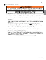
Page 69: ... actuelles pour les maisons mobiles équipées au gaz CAN CSA Z240 SÉRIE MM au Canada ou selon les normes ANSI Z223 1 et NFPA 54 aux États Unis ALLUMEZ TOUJOURS LA VEILLEUSE QUE CE SOIT POUR LA PREMIÈRE FOIS OU LORSQUE L APPROVISIONNEMENT EN GAZ EST ÉPUISÉ AVEC LA PORTE VITRÉE OUVERTE OU RETIRÉE PRÉVOYEZ UN ACCÈS SUFFISANT POUR ENTRETENIR ET OPÉRER L APPAREIL ASSUREZ VOUS D UNE QUANTITÉ SUFFISANTE D...

Page 70: ...imentation en gaz 7 de colonne d eau 17mb 13 de colonne d eau 32mb Pression au collecteur lorsque le gaz circule 3 5 de colonne d eau 9mb 10 de colonne d eau 25mb POUR VOTRE SATISFACTION CET APPAREIL A ÉTÉ MIS À L ESSAI POUR CONFIRMER SON FONCTIONNEMENT ET SA QUALITÉ 4 1B Tant que les distances requises pour les dégagements aux matériaux combustibles sont respectées le meilleur endroit pour un app...

Page 71: ...UR INSTALLATION DANS UNE MAISON MOBILE SI SON INSTALLATION CONFORME AUX EXIGENCES DE LA NORME CAN CSA Z240MH SÉRIE DE MAISONS MOBILES ÉQUIPÉES AU GAZ EN VIGEUR AU CANADA OU AUX ÉTATS UNIS DE LA NORME DE SECURITE ET DE CONSTRUCTION DE MAISONS MANUFACTUREE TITRE 24 CFR SECTION 3280 DANS LE CAS OU CETTE NORME D ÉTATS UNIS NE PEUT ETRE APPLIQUÉE SE REFERER A LA NORME RELATIVE AU CRITÈRE DE MESURES DE ...

Page 72: ...on ou un écran thermique de grenier lorsque les murs intérieurs le plancher ou le plafond sont traversés NOTE Si pour une raison quelconque le système d évents de prise d air est démonté réinstallez et rescellez le selon les instructions fournies dans l installation initiale 7 7 AVERTISSEMENT RISQUE D INCENDIE CONSERVEZ LES DÉGAGEMENTS NÉCESSAIRES AU CONDUIT D ÉVENT ET À L APPAREIL SI LE SYSTÈME D...

Page 73: ...rifiez la prise d air de la terminaison au moins une fois l an pour vous assurer qu elle n est pas obstruée ni endommagée La longueur maximale permise pour un évent vertical est de 40 pieds 12 2m la longueur minimale permise pour un évent vertical est de 3 pieds 0 9m Le nombre maximal de raccordements de 8 203 2m est de trois horizontalement ou verticalement excluant les raccordements au foyer et ...

Page 74: ... 19 14 FR 3 2 INSTALLATIONS TYPIQUES D ÉVENTS Voir la section ÉVACUATION 45 8 18 457mm MAXIMUM 24 610mm MIN 71 1 2 1816mm PLUS RISE 16 406mm MINIMUM 40 FEET 12m MAXIMUM 3 FEET 0 9m MINIMUM 47 1 2 1207mm 47 1 2 1207mm ...

Page 75: ... murs adjacents incluant les maisons voisines P 8 2 4m 8 2 4m Le toit doit être incombustible et sans ouvertures Q 3 0 9m 3 0 9m Voir le tableau pour les dimensions d un mur plus large R 6 1 8m 6 1 8m Voir le tableau pour les dimensions d un mur plus profond La terminaison ne doit pas être installée sur quelconque mur ayant une ouverture entre la terminaison et le côté ouvert de la structure S 12 ...

Page 76: ... 4 2 fois la course verticale plus grande ou égale à la course horizontale 3 fois la course verticale plus grande ou égale à la course horizontale ÉVACUATION SUR LE DESSUS 14 1 Les symboles suivants sont utilisés dans le calcul et les exemples d évacuation plus grand que plus grand ou égal à plus petit que plus petit ou égal à HT total de la longueur des courses horizontales Hr et des déviations H...

Page 77: ...tion exige plus d un coude de 90 les formules suivantes s appliquent Formule 1 HT VT Formule 2 HT VT 40 pieds 12 2m Exemple V1 3 PI 0 9m V2 8 PI 2 4m VT V1 V2 3PI 0 9m 8PI 2 4m 11PI 3 4m H1 2 5 PI 0 8m H2 2 PI 0 6m HR H1 H2 2 5PI 0 8m 2PI 0 6m 4 5 PI 1 4m HO 0 03 trois coudes 90 90 0 03 270 90 5 4 PI 1 6m HT HR HO 4 5PI 1 4m 5 4PI 1 6m 9 9 PI 3m HT VT 9 9PI 3m 11PI 3 4m 20 9 PI 6 4m Formule 1 HT V...

Page 78: ...9m H2 5 PI 1 5m HR H1 H2 3PI 0 9m 5PI 1 5m 8PI 2 4m HO 03 two 90 elbows 90 03 180 90 2 7PI 0 8m HT HR HO 8PI 2 4m 2 7PI 0 8m 10 7PI 3 3m HT VT 10 7PI 3 3m 6PI 1 8m 16 7PI 5 1m Formule 1 HT 4 2 VT 4 2 VT 4 2PI 1 3m x 6PI 1 8m 25 2PI 7 7m 10 7PI 3 3m 25 2PI 7 7m Formule 2 HT VT 24 75 PI 7 5m 16 7PI 5 1m 24 75PI 7 5m Puisque les deux formules sont respectées cette configuration d évacuation est accep...

Page 79: ... Exemple V1 5 PI 1 5m V2 6 PI 1 8m V3 10 PI 3 1m VT V1 V2 V3 5PI 1 5m 6PI 1 8m 10PI 3 1m 21 PI 6 4m H1 8 PI 2 4m H2 2 5 PI 0 8m HR H1 H2 8 PI 2 4m 2 5 PI 0 8m 10 5 PI 3 2m HO 0 03 quatre coudes 90 90 0 03 360 90 8 1 PI 2 5m HT HR HO 10 5PI 3 2m 8 1PI 2 5m 18 6 PI 5 7m HT VT 18 6PI 5 7m 21PI 6 4m 39 6 PI 12 1m Formule 1 HT VT 18 6PI 5 7m 21PI 6 4m Formule 2 HT VT 40 PI 12 2m 39 6 PI 12 1m 40 PI 12 ...

Page 80: ... PI 2 4m HO 0 03 quatre coudes 90 90 0 03 360 90 8 1 PI 2 5m HT HR HO 8 PI 2 4m 8 1 PI 2 5m 16 1 PI 4 9m HT VT 16 1PI 4 9m 4 5PI 1 4m 20 6 PI 6 3m Formule 1 HT 3VT 3VT 3PI 0 9m x 4 5PI 1 4m 13 5 PI 4 1m 16 1 PI 4 9m 13 5 PI 4 1m Puisque cette formule n est pas respectée cette configuration d évacuation est inacceptable Formule 2 HT VT 40 pieds 12 2m 20 6 PI 6 3m 40 PI 12 2m Puisque seulement la fo...

Page 81: ...MPÉRATURE MILL PAC W573 0007 NON FOURNI À L EXCEPTION DU RACCORDEMENT DU CONDUIT D ÉVACUATION À LA BUSE DE L APPAREIL QUI DOIT ÊTRE SCELLÉ AVEC LE SCELLANT MILL PAC SI VOUS UTILISEZ DES COLLIERS POUR TUYAU POUR RACCORDER LES COMPOSANTS D ÉVACUATION VOUS DEVEZ AUSSI INSTALLER TROIS VIS POUR VOUS ASSURER QUE LE RACCORDEMENT NE SE DÉFASSE PAS NE SERREZ PAS LA GAINE FLEXIBLE RISQUE D INCENDIE D EXPLOS...

Page 82: ...1 2 215 9mm de profond mais doit se prolonger sur toute la profondeur du mur combustible A Appliquez un joint de calfeutrage non fourni tout autour de la bordure de la face intérieure de l espaceur coupe feu installez l espaceur coupe feu contre le trou et fixez à l aide des quatre vis fournies dans le sac de votre manuel B Une fois que le conduit d évent est en place appliquez du scellant à haute...

Page 83: ... que l espaceur coupe feu et le protecteur de conduit d évacuation conservent le dégagement nécessaire aux matériaux combustibles Une fois que le conduit d évacuation est en place appliquez un agent d étanchéité entre le conduit d évacuation et l espaceur coupe feu C Dans le grenier faites glisser le collet de conduit d évacuation vers le bas afin de recouvrir l extrémité ouverte du protecteur de ...

Page 84: ...soutenant la terminaison les inscriptions étant à l endroit et lisibles fixez la au mur extérieur et rendez la étanche en la scellant avec du calfeutrage non fourni D Si plus de sections de gaine doivent être utilisées pour atteindre l appareil raccordez les ensemble tel qu illustré Les courses horizontales et verticales du système d évacuation doivent être supportées chaque 3 pieds 0 9m approxima...

Page 85: ...naison en laissant un minimum de 3 4 19 1mm de connecteur de terminaison visible au dessus du haut du solin Glissez le solin sous les côtés et le bord supérieur des bardeaux Assurez vous que le connecteur de terminaison est bien centré dans le solin en laissant une marge de 3 4 19 1mm tout autour Fixez le au toit Ne clouez pas à travers la partie inférieure du solin Imperméabilisez le en le scella...

Page 86: ...tion Un ensemble de conversion est fourni avec l appareil pour maison mobile 29 1A Cet appareil homologué pour les maisons mobiles et préfabriquées possède des éléments de fixation L appareil est muni de deux trous de 6 4mm de diamètre situés aux coins avant gauche et droit de la base Lors d une installation dans une maison mobile l appareil doit être fixé au plancher Fixez à l aide de vis 10 à tê...

Page 87: ...eau savonneuse N utilisez pas une flamme nue AVERTISSEMENT RISQUE D INCENDIE D EXPLOSION OU D ASPHYXIE ASSUREZ VOUS QU IL N Y AIT AUCUNE SOURCE D ALLUMAGE COMME DES ÉTINCELLES OU UNE FLAMME NUE SOUTENEZ LE CONTRÔLE DU GAZ LORSQUE VOUS ATTACHEZ LE TUYAU POUR ÉVITER DE PLIER LA CON DUITE DE GAZ ALLUMEZ TOUJOURS LA VEILLEUSE QUE CE SOIT POUR LA PREMIÈRE FOIS OU LORSQUE L APPROVISIONNEMENT EN GAZ EST ...

Page 88: ...X COMBUSTIBLES DOIVENT ÊTRE MAINTENUS L ENCEINTE DE L APPAREIL DOIT RESPECTER LA HAUTEUR MINIMALE REQUISE MESUREZ À PARTIR DE LA BASE DE L APPAREIL SI DES ENSEMBLES DE MONTANTS EN ACIER AVEC PANNEAU DE CIMENT SONT FOURNIS OU SPÉCIFIÉ DANS LES INSTRUCTIONS D INSTALLATION ILS DOIVENT ÊTRE INSTALLÉS LES MATÉRIAUX DE FINITION DOIVENT ÊTRE NON COMBUSTIBLES PLACER ÉCLAT AVEC LA FACE DE L APPAREIL ÉTENDU...

Page 89: ... matériaux de finition pour maintenir les dégagements IMPORTANT Avant d effectuer la finition vérifiez le fonctionnement de l appareil à l aide de la télécommande en testant chacun des différents modes Voir la section FONCTIONNEMENT Si un dépannage s avère nécessaire l accès aux contrôles peut se faire par le panneau d accès de préinstallation ...

Page 90: ...90 W415 1371 09 19 14 FR 293 8 746mm 573 8 1457mm 293 8 746mm 573 8 1457mm 6 152mm 573 8 1457mm 2 51mm 1021 4 2597mm 691 8 1755mm ...

Page 91: ...éger mouvement lors du fonctionnement normal de l appareil Si du coulis est utilisé entre les carreaux un coulis à base de polymère tel que Mapei Ultracolour plus est recommandé Apprêt Peinture Pour une surface peinte utilisez un apprêt au latex 100 acrylique et une couche de finition AVERTISSEMENT UNE FINITION INCOMBUSTIBLE COMME DE LA BRIQUE DU MARBRE DU GRANITE ETC EST REQUISE IL EST INTERDIT D...

Page 92: ... réglé à partir de l unité de 1 3 4 44mm comme indiqué ci dessous 1 3 4 44mm 1 3 4 44mm Matériau de Finition Épais Matériau de finition Mince NOTE Dimensions d encadrement varient en fonction de l épaisseur du matériau de finition 5 1 1 INSTALLATION DES PANNEAUX DE BÉTON LATÉRAUX ET CENTRAUX ...

Page 93: ... MINIMALEDE 711 2 1816mm NOTE UN COMPOSÉ À JOINTS ET DU RUBAN À JOINTS RÉSISTANTS À LA CHALEUR ET AUX CRAQUELURES DEVRAIENT ÊTRE UTILISÉS LORSQUE VOUS POSEZ DU RUBAN À JOINTS ET QUE VOUS COMBLEZ DES JOINTS ÉCRAN DE PROTECTION Consultezlasection ÉVACUATION Àl intérieurdel enceinte undégagementde11 276mm estrequisentrelehautduconduitd évacuationetlesmaté riauxcombustibles Pourtoutautredégagementàl i...

Page 94: ...einte undégagementde11 276mm estrequisentrelehautduconduitd évacuationetlesmatériaux combustibles Pourtoutautredégagementàl intérieurdel enceinte ycomprisl endroitoùleconduitd évacuationsortdel enceinte l espacementrequisestde11 2 38mm àpartirdescôtésetdubas de41 2 114mm àpartirduhautpourlessectionshorizon tales etde1 25mm pourlessectionsverticales Consultezlasection ÉVACUATION IMPORTANT L ASSEMBL...

Page 95: ... 1067mm B 6 152mm 2 51mm C 8 203mm 4 102mm D 10 254mm 6 152mm E 12 305mm 8 203mm AVERTISSEMENT RISQUE D INCENDIE CONSERVEZ TOUS LES DÉGAGEMENTS AUX MATÉRIAUX COMBUSTIBLES SPÉCIFIÉS NE PAS RESPECTER CES INSTRUCTIONS PEUT CAUSER UN INCENDIE OU UNE SURCHAUFFE ASSUREZ VOUS QUE TOUS LES DÉGAGEMENTS ARRIÈRE CÔTÉS DESSUS ÉVENTS TABLETTE FAÇADE ETC SONT RESPECTÉS À LA LETTRE LORSQUE VOUS UTILISEZ DE LA PE...

Page 96: ...n Si vous utilisez un moulure optionelle un dégagement de 2 24 5mm au dessus du cadre est requis pour une projection maximale de 2 24 5mm Si des projections plus grandes sont requises augmentez les dégagements du moulure optionelle de 2 24 5mm pour chaque pouce supplémentaire de projection B B A A 1 4 101 6mm 0 PORTE SOMMET DE L APPAREIL SECTION A A SECTION B B 6 152 4mm 4 101 6mm 2 50 8mm 2 50 8m...

Page 97: ...SE TROUVENT PAS EN DEÇÀ DE LA DIMENSION SPÉCIFIÉE TEL QU ILLUSTRÉ COMME ALTERNATIVE VOUS POUVEZ UTILISER LE PANNEAU DE GYPSE COMME FINITION POUR VOTRE APPAREIL VOIR LES ILLUSTRATIONS À SUIVRE NE FRAPPEZ PAS NE CLAQUEZ PAS ET N ÉGRATIGNEZ PAS LA PORTE VITRÉE NE FAITES PAS FONCTIONNER L APPAREIL LORSQUE LA PORTE VITRÉE EST ENLEVÉE FISSURÉE BRISÉE OU ÉGRATIGNÉE LES MATÉRIAUX DE FAÇADE OU DE FINITION ...

Page 98: ...quet en avant et vers le haut puis hors de l entaille dans la porte comme illustré Répéter 3 fois C Quand les 4 loquets sont relâchés tirer la porte en avant et lors de l appareil D Renverser ce processus pour fixez la porte IMPORTANT Lorsque les loquets sont verrouillés vérifiez que la porte est bien fixée et qu elle ne tombera pas avant de la lâcher LATCHES LES 4 LOQUETS SONT ILLUSTRÉE CI DESSOU...

Page 99: ...AITS DU LOQUET DE PORTE B Glissez la porte vitrée vers l avant Elle reposera sur les glissières de porte fixées à l appareil refer to Figure 1 C Soulevez la porte vitrée hors des glissières et retirez la de l appareil D Renverser ce processus pour installer l ecran de protection 6 3 ENLÈVEMENT ET INSTALLATION DE LA PORTE VITRÉE ...

Page 100: ...100 W415 1371 09 19 14 FR 6 5 MISE EN PLACE DU LOGO 6 4 INSTALLATION DU BRÛLEUR Voir les instructions accompagnant l assemblage du brûleur vendu séparément LOGO SAFETY BARRIER ÉCRAN DE PROTECTION ...

Page 101: ...STALLER TROIS VIS POUR VOUS ASSURER QUE LE RACCORDEMENT NE SE DÉFASSE PAS NE SERREZ PAS LA GAINE FLEXIBLE RISQUE D INCENDIE D EXPLOSION OU D ASPHYXIE SI L ENSEMBLE DU SYSTÈME DE CONDUIT D ÉVENT N EST PAS ADÉQUATEMENT SOUTENU IL RISQUE DE FLÉCHIR OU DE SE SÉPARER UTILISEZ DES SUPPORTS DE CONDUIT ET RACCORDEZ LES SECTIONS DE CONDUITS SELON LES INSTRUCTIONS D INSTALLATION RISQUE D INCENDIE ÉVITEZ QUE...

Page 102: ...ssible pour programmer la télécommande Installez le récepteur dans un boîtier électrique standard Déterminez un emplacement approprié et installez le boîtier électrique NOTE Assurez vous que l interrupteur à trois position est placer en position REMOTE milieu BOUTON DE RÉINITILISATION PROGRAMMATION PRG 4 AA Batteries SAFETY BARRIER 4 AA Batteries ÉCRAN DE PROTECTION ...

Page 103: ...L ÉTAT INITIAL W190 0048 RÉCEPTEUR HARNAIS DE FILS ASSEMBLAGE DE PILOTE CONNECTEUR INTERRUPTEUR ON OFF PRINCIPAL ÉTINCELLE GAZ SOUPAPE BRÛLEUR PILOTE LUMIÈRE SOUFFLERIE NATTES LUMIÈRES VARIABLE COMMUTATEUR DE CORDON D ALIMENTATION PRINCIPALE FONDER ETOILE DE L APPAREIL NOTE Pour votre protection contre les risques de chocs électriques cet appareil est muni d une fiche à trois broches et devrait êt...

Page 104: ...rale C Appuyez sur le bouton réinitialisation programmation utilisez un objet de petite taille comme un trombone afin d atteindre le bouton identifié PRG tel qu illustré ci dessous D Le bloc piles émettra trois bips pour indiquer qu il est prêt à être synchronisé avec la télécommande E Installez trois piles AAA dans la télécommande comme illustré ci dessous puis appuyez sur la touche ON Le bloc pi...

Page 105: ...e la flamme soit éteinte La touche haut augmentera la hauteur de la flamme chaque fois qu elle est enfoncée Si la touche haut est enfoncée lorsque le système est en marche mais que la flamme est éteinte la flamme s allumera en position élevée Un seul bip confirmera la réception de la commande 35 8A 76 F OFF 76 F 76 F 76 F Hi FLAMME ÉTEINTE FLAMME AU NIVEAU 1 FLAMME AU NIVEAU 5 FLAMME AU NIVEAU 6 H...

Page 106: ...du thermostat de la télécommande etc Lorsque les piles de la télécommande sont faibles l icône de pile apparaîtra sur l afficheur ACL avant que les piles soient complètement déchargées Une fois que les piles sont remplacées cette icône disparaîtra Non applicable lorsque branché dans du 110 V Lorsque les piles du récepteur sont faibles celui ci n émettra pas de bip lorsqu il recevra une commande MA...

Page 107: ...issez l alimentation électrique à l appareil et remettez les piles dans l émetteur 11 Appuyez sur le bouton ON de la télécommande Vous devriez entendre un bip du récepteur vous indiquant que la communication est bonne Pour activer le récepteur référez vous à la section FONCTIONNEMENT DE L APPAREIL INSTRUCTIONS POUR COUPER LE GAZ 1 Coupez l alimentation électrique à l appareil si un travail d entre...

Page 108: ...t S il y a des traces de peinture ou de surpulvérisation enlevez les de l assemblage de la veilleuse ou remplacez le Une toile d émeri ou du papier sablé fins peut être utilisé pour enlever la peinture sur la hotte de la veilleuse sur l électrode et sur le capteur de flamme 39 1C A B VIS DE LA VEILLEUSE Pression Gaz Naturel pouces Gaz Naturel millibars Propane pouces Propane millibars Arrivée 7 mi...

Page 109: ... préréglée en usine selon le tableau ci dessous Indépendamment de l orientation du venturi plus le volet est fermé plus la flamme est jaune et aura tendance à causer des dépôts de carbone Plus le volet est ouvert plus la flamme est bleue et plus elle a tendance à se détacher des orifices du brûleur La flamme peut ne pas être jaune immé diatement allouez de 15 à 30 minutes pour que la couleur final...

Page 110: ...et ou le thermocouple thermopile et qu elle atteigne le brûleur E Remettez en place les bûches les roches ou la vitre nettoyées si équipé Omettre de positionner les composants décoratifs adéquatement peut causer des dépots de carbone qui peuvent se déposer dans des endroits de séjour avoisinants F Vérifiez si le brûleur principal allume sur tous les orifices lorsque le bouton de contrôle du gaz es...

Page 111: ...r Pour les braises de verre suivez les instructions de prénettoyage Enlevez aussi tout dépôt se trouvant sur l assemblage de la veilleuse et aussi s il y a lieu sur la thermopile le thermocouple le capteur de flamme et l allumeur NOTE Vous devrez possiblement nettoyer le capteur de flamme à l aide d une morceau de de laine d acier ou Scotch Brite afin de retirer toute trace d oxydation Nettoyez l ...

Page 112: ...teau à de l appareil suivez les instructions pour l enlèvement de l ensembles décoratifs sous ENLÈVEMENT REMPLACEMENT DES ENSEMBLES DÉCORATIFS section B Retirez le brique du côté droite panneau de porcelaine suivez les instructions pour l enlèvement de l ensembles décoratifs sous ENLÈVEMENT DU PANNEAU DE BRIQUE PORCELAINE section C Pour enlèver les plateau de verre pour enlèver le brûleur de verre...

Page 113: ...u briques de la panneau situées du côté supérieur gauche de l appareil B Retirez les panneau gauche NOTE Le soin devrait être avec le déflecteur arrière comme elle repose sur les panneaux gauche et droit C Retirez l arriere déflecteur D Répétez l étape A pour le côté droit E Retirez les panneau gauche en le soulevant hors du support du panneau arrière A Retirez les 4 vis de fixation du côté supéri...

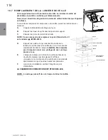
Page 114: ...z les quatre vis qui retiennent le cadre de la lentille Ce cadre retient la lentille de verre Vous pouvez maintenant accéder à l ampoule NOTE Ne manipulez pas l ampoule à main nue protégez la avec un linge propre et sec E L ampoule s enlève en la tirant à la verticale hors de la douille Remplacez par des pièces Wolf Steel uniquement car l ampoule et la lentille sont des produits spécialement conçu...

Page 115: ...s ou du vinaigre et un linge pour nettoyer Si la surface plaquée n est pas bien nettoyée avant le premier allumage de l appareil elle risque de rester marquée en permanence Une fois que la surface plaquée aura chauffé les traces de doigts et le gras n affecteront plus la surface et très peu d entretien sera requis vous n aurez qu à l essuyer au besoin Une combustion prolongée à haute température a...

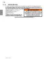
Page 116: ...ORER LA DEMANDE Lorsque vous commandez des pièces donnez toujours l information suivante Modèle et numéro de série de l appareil Date d installation de l appareil Numéro de la pièce Description de la pièce Fini IDENTIFIE LES ARTICLES QUI NE SONT PAS ILLUSTRÉS POUR PLUS D INFORMATION CONTACTEZ VOTRE DÉTAILLANT AUTORISÉ AVERTISSEMENT OMETTRE DE POSITIONNER LES PIÈCES CONFORMÉMENT AU MANUEL OU D UTIL...

Page 117: ...0 0011 GLISSIÈRE DE 2 X2 6 W010 3139 ASSEMBLAGE DE DÉTENDEUR DE PORTE X2 7 W010 3293 ASSEMBLAGE DU LOQUET DE PORTE X4 REF PART DESCRIPTION 8 W010 3151 L ASSEMBLAGE DE LA SOUPAPE GN 9 W707 0006 TRANSFORMATEUR 10 W350 0464 BOÎTE ÉLÉCTRIQUE 11 W460 0006 RÉCEPTACLE 12 W500 0443 BOÎTE DE JONCTION 1 2 3 4 5 6 7 8 9 10 11 CES ARTICLES PEUT DIFFÉRER DE CELLE ILLUSTRÉ POUR LES PIÉCES DE REMPLACEMENT VOIR L...

Page 118: ...LES PIÉCES DE REMPLACEMENT VOIR BRÛLEUR BÛCHES DE B52NL 1 POUR LES PIÉCES DE REMPLACEMENT VOIR L ASSEMBLAGE DE LA SOUPAPE BÛCHES AVANT DROITE GL 695 BÛCHES AVANT GAUCHE GL 695 BÛCHE ARRIÈRE DROITE GL 695 BÛCHE ARRIÈRE GAUCHE GL 695 BRAISES VITRIFIÉES ADAPTEUR DU TERMINAISON À ÉVACUATION TERMINAISON À ÉVACUATION MÉCANIQUE BASE DU DEFLECTOR VERRE BRÛLEUR ENSEMBLE DE BÛCHES HDX52 1 ASSEMBLAGE DE BRÛL...

Page 119: ...26 BRIQUE EN FIBRE DU HERRINGBONE GD854KT W090 0221 PANNEAU DE VICTORIEN DU GAUCHE GD854KT 16 W090 0234 PANNEAU DE LEDGESTONE GD859KT W090 0235 PANNEAU LEDGESTONE CENTRAL GD859KT W090 0236 PANNEAU DE LEDGESTONE GD859KT W090 0232 PANNEAU DE BRIQUE NEW PORT DU DROITE GD855KT W090 0231 PANNEAU DE BRIQUE CENTRALE GD855KT W090 0233 2 3 4 GD854KT 1 W090 0230 BRIQUE EN FIBRE DU NEW PORT GD855KT 11 10 GD8...

Page 120: ... 1398 13 14 W255 0002 15 W500 0767 16 W456 0017 17 W456 0043 18 W080 1483 W080 1375 W655 0553 SUPPORTS DE BRÛLEUR SUPPORT DU BRAISES GAUCHE 8 9 W080 1380 11 W010 2900 ASSEMBLAGE DE VEILLEUSE PL W080 1392 ASSEMBLAGE DE GRILLE ASSEMBLAGE DE BRÛLEUR SUPPORT DE BRÛLEUR GAUCHE JOINT D ÉTANCHÉITÉ DU VENTURI SUPPORT DES BÛCHES PANNEAU DE SUPPORTS BOÎTIER DE VEILLEUSE SUPPORT DE VEILLEUSE SUPPORT DE BRÛLE...

Page 121: ...79 16 W080 1478 9 W080 1480 8 W010 2900 17 W100 0167 CES ARTICLES PEUT DIFFÉRER DE CELLE ILLUSTRÉ SUPPORT DU BOL MOULURE DE BOL JOINT D ÉTANCHÉITÉ DU VENTURI VENTURI SUPPORT DE BRÛLEUR GAUCHE COUVERCLE DE VEILLEUSE ASSEMBLAGE DU BOL ASSEMBLAGE DE VEILLEUSE GN SUPPORT DE VEILLEUSE ASSEMBLAGE DE VEILLEUSE LP ASSEMBLAGE DE BRÛLEUR À PLATEAU RACCORD POUR TUBE PLAQUE DE SUPPORT DU VENTURI INJECTEUR DE ...

Page 122: ...EMBLAGE DE LA PORTE 3 N402 0001 L ASSEMBLAGE DE LUMIÈRE 4 W290 0080 PLAQUE DE RECOUVREMENT DU JOINT D ÉTANCHÉITÉ 5 W280 0071 PLAQUE DE RECOUVREMENT DU LENTILLE REF PART DESCRIPTION 6 W300 0067 VERRE 7 W290 0239 8 W500 0756 RETENUE DU PORTE CES ARTICLES PEUT DIFFÉRER DE CELLE ILLUSTRÉ PORTE DE JOINT D ÉTANCHÉITÉ 16 0 ASSEMBLAGE DE LA PORTE ...

Page 123: ... PANNEAU DE CONTRÔLE 7 W010 3319 ASSEMBLAGE DE SOUPAPE PL AVEC RACCORDS 8 W350 0737 PANNEAU DE CONTRÔLE DU BOÎTIER REF PART DESCRIPTION 9 W500 0766 PANNEAU DE CONTRÔLE DU PLAQUE DE RECOUVREMENT 10 W255 0021 TUBE DE VEILLEUSE RACCORD 11 W240 0010 DOUBLE RACCORD D ÉLECTRODE 12 W350 0464 BOÎTE ÉLECTRIQUE 13 W460 0006 PRISE DOUBLE 14 W750 0268 HARNAIS DE FILS 15 W350 0655 TÉLÉCOMMANDE L ASSEMBLAGE DE ...

Page 124: ...ER NE SERREZ PAS TROP FORT Vérifiez pour des fuites en appliquant une solution d eau savonneuse Du carbone se dépose sur la vitre les bûches les roches les composants décoratifs ou les parois de la chambre de combustion Le volet d air est bloqué Assurez vous que l ouverture du volet d air n est pas bloquée par des fibres ou autres obstructions La flamme effleure la vitre les bûches les roches les ...

Page 125: ...une des quatre méthodes suivantes pour réinitialiser le système 1 Pour réinitialiser la boîte d allumage lorsqu elle a été verrouillée coupez l alimentation électrique et retirez les piles s il y a lieu du récepteur 2 Pour réinitialiser le tableau DFC lorsque celui ci se trouve en mode verrouillé et que la DEL clignote trois fois à l aide du bouton MARCHE ARRÊT de l émetteur Étape 1 Éteignez le sy...

Page 126: ... Un mauvais injecteur ou une pression d arrivée trop élevée peut causer la flamme de la veilleuse à se détacher La tige de la sonde a possiblement besoin d être nettoyée Mauvaise mise à la terre entre l assemblage de la veilleuse et la soupape de gaz Vérifiez si le harnais de fils est solidement branché au module Veilleuse endommagée ou tige de sonde salie Vérifiez si l isolateur de céramique auto...

Page 127: ...sation des produits chimiques ou produits d entretien nuisibles ne seront pas la responsabilité de NAPOLÉON Toutes les pièces remplacées en vertu de la politique de Garantie à vie limitée du Président ne peuvent faire l objet que d une seule réclamation Durant les dix premières années NAPOLÉON remplacera ou réparera les pièces défectueuses qui sont couvertes par la garantie à vie limitée à sa disc...

Page 128: ...s électriques Foyers extérieurs Grils à gaz de qualité Foyers Chauffage et Climatisation Grils composez 514 737 6294 napoleonproducts com 7200 Route Transcanadienne Montréal Québec H4T 1A3 24 Napoleon Road Barrie Ontario Canada L4M 0G8 214 Bayview Drive Barrie Ontario Canada L4N 4Y8 103 Miller Drive Crittenden Kentucky USA 41030 ...

Reviews: