background image

W415-4188 / B-0 / 11.13.23

EN

4  

table of contents

1.0  general information 

5

1.1 dimensions 

5

1.2 

listing approvals 

6

1.3 

general instructions 

6

1.4 

unpacking and testing the appliance 

7

1.5 

hardware list 

8

1.6 

rating plate information 

8

1.7 

label location 

9

2.0  installation  

10

2.1 

minimum mantel clearances  

11

2.2 

rough framing 

11

2.3 

three-sided, two-sided, and single-sided viewing pre-installation 

12

2.4  

three-sided, two-sided, and single-sided viewing installation 

13

2.4.1  three-sided viewing installation 

13

2.4.2  two-sided viewing installation 

13

2.4.3  single-sided viewing installation 

14

2.5  

three-sided, two-sided, and single-sided viewing post-installation 

14

3.0  electrical information 

15

3.1 

120V hard wiring  

16

3.2 

240V hard wiring  

17

3.3 

wall mount controller installation 

17

4.0  finishing material 

18

4.1 

finishing materials 

18

4.1.1  screw-safe areas 

18

4.2 

installing combustible and non-combustible materials  

18

4.3 

media installation 

19

4.3.1  log set and media installation 

19

4.4 

front glass installation and removal  

20

5.0  wiring diagram 

     21

6.0 operation 

22

6.1 

operating control panel 

22

6.2 

operating remote control 

23

6.3 

operating wall-mount control 

26

7.0  napoleon connectivity 

27

7.1 

operating remote control 

28

7.2 

using the app 

30

7.2.2  heat setting 

30

7.2.1  power setting 

30

7.2.3  ember bed setting 

31

7.2.4  flame setting 

31

7.2.5  accessory lights settings 

32

7.2.6  timer settings 

32

8.0 maintenance 

33

8.1 cleaning 

33

8.2 

heater lock out switch                                                                                                                 33

9.0   replacement parts 

34

9.1 NEFL65LCD-3SV 

35

10.0    troubleshooting 

36

11.0    warranty 

38

The information throughout this manual is believed to be correct at the time of printing. Wolf Steel Ltd. reserves 

the right to change or modify any information within this manual at any time without notice. Changes, other than 

editorial, are denoted by a vertical line in the margin.

note:

Summary of Contents for Luminex Series

Page 1: ...FETY INFORMATION Do not store or use gasoline or other flammable vapors and liquids in the vicinity of this or any other appliance FIRE OR EXPLOSION HAZARD If the information in these instructions are...

Page 2: ...ified service technician to inspect the appliance and to replace any part of the control system which has been under water If equipped with a glass door do not operate the appliance with the glass doo...

Page 3: ...for use only with the optional accessories listed in these instructions Use of optional accessories not specifically tested for this appliance could void the warranty and or result in a safety hazard...

Page 4: ...g materials 18 4 1 1 screw safe areas 18 4 2 installing combustible and non combustible materials 18 4 3 media installation 19 4 3 1 log set and media installation 19 4 4 front glass installation and...

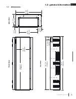
Page 5: ...4188 B 0 11 13 23 16 3 4 426mm 64 15 16 1650mm 65 1 16 1653mm 66 1 4 1683mm 3 13 16 97mm 12 1 16 307mm 9 16 15mm 25 3 8 644mm 18 3 8 467mm 3 9 16 90mm 1 0 general information front view side view top...

Page 6: ...new electric appliance has been designed to operate at temperatures between 5 C 41 F and 35 C 95 F During the colder winter months allow the appliance to reach room temperature before turning it on T...

Page 7: ...nsure to unpack this appliance with 2 people Reference the hardware list see hardware list section to prepare for installation 1 4 unpacking and testing the appliance note Exact packaging location may...

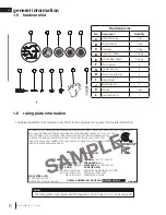
Page 8: ...N STUDIO APPROPRI POUR INSTALLATION DANS UNE MAISON MOBILE VOLTAGE 120V AC 240V AC TENSION 120V AC 240V AC FREQUENCY 60Hz FR QUENCE 60Hz POWER 1500W 3000W PUISSANCE 1500W 3000W DATE CODE XXXXX CODE DE...

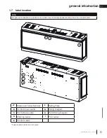
Page 9: ...ng Plate B Do Not Cover Label G Wiring Diagram C Hot Surface Label H Hard Wiring Diagram D Warning Label I FCC Label E Caution Label note Images are for illustrative purposes only Labels may not alway...

Page 10: ...ingle sided Appliance is fully recessed into the wall Front view only Left and right side views are covered Appliance is fully recessed into the wall with one side open Front view and left right side...

Page 11: ...ing wall framing Hard wire location Appliance is NOT load bearing Carefully consider the weight of finishing materials when constructing rough framing note Ensure the installation complies with all lo...

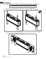
Page 12: ...the 4 metal brackets supplied using the 8 screws and washers previously removed Fig 3 2 Fig 3 1 Fig 3 2 C x 4 3 Remove the side trims and side panels from both sides of the appliance by removing the 1...

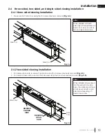
Page 13: ...d viewing installation 2 4 1 three sided viewing installation 2 4 2 two sided viewing installation 1 Re secure both side trims using the 12 screws previously removed Fig 3 4 Side Trim Fig 3 4 Side Tri...

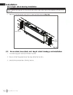
Page 14: ...eft and right sides covered the appliance will have a front view only 1 Complete wiring see electrical information section 2 Secure and test the appliance see securing and testing section 3 Install fi...

Page 15: ...er by removing the fasteners as shown 1 Locate the desired 2 conductor or 3 conductor wire cable to the top right side of the enclosure for the hard wiring installation based on the desired 120V or 24...

Page 16: ...Tighten the screw note If installing with the optional wall mount controller plug in the wire harness connection to the 4 pin connector located to the left of hard wire terminal block 4 Make sure all...

Page 17: ...the screw note If installing with the optional wall mount controller plug in the wire harness connection to the 4 pin connector located to the left of the hard wire terminal block 5 Make sure all conn...

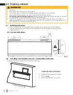
Page 18: ...netrate into the blower bearings causing irreparable damage Care must be taken to prevent drywall dust from coming into contact with the blower or its compartment Any damage resulting from this condit...

Page 19: ...cannot be covered in any circumstances WARNING 1 2 3 4 5 6 7 4 3 1 5 6 7 Fig 7 4 3 1 log set and media installation 1 Start by laying out the 2 types of glass along the media bed Mix the 2 colours to...

Page 20: ...led or removed unplug the appliance and wait until appliance is cool to the touch Glass can be heavy and fragile so handle with care WARNING Once the screws are removed from the bracket carefully remo...

Page 21: ...urn off the appliance completely and let cool before servicing Only a qualified service person should service and repair this electric appliance WARNING Carte d alimentation cran DEL cran DEL cran DEL...

Page 22: ...the appliance is working under ECO mode energy saving Boost Mode Indicator Indicate the appliance is working under Boost mode Wi Fi Indicator Indicates the appliance is connected to the wireless netwo...

Page 23: ...isabled by holding the button for 3s When the heater function is disabled LOC will be displayed 6 2 operating remote control Features Power standby Heater setting H 0 FAN H 1 ECO mode Boost mode Tempe...

Page 24: ...1 to 5 to set the time ON OFF schedule every day Note During the time and scheduling setting only when the IR receiver is aimed the signal can be received by PCB When the signal is received successfu...

Page 25: ...n ember bed color icon will start to flash Use to change settings L01 L02 L13 L C Cycle Ember Bed Brightness Press the button once flame brightness icon will start to flash Use to change settings F 3...

Page 26: ...eed Note Heater control function can be enabled disabled by holding the button for 3s When the heater function is disabled LOC will be displayed Thermostat Control Press this button once temperature s...

Page 27: ...13 0 Register an account with the Napoleon Home App OR sign in using your Facebook Google or Apple account information Enter user information and create a password for the account Select the country i...

Page 28: ...ed in and turned on Fig 1 2 Press and hold the Wi Fi control button on the appliance control panel for 8 seconds Fig 2 The Wi Fi icon on the touch panel will start flashing note Fig 1 Fig 2 3 Select A...

Page 29: ...rom the list Fig 5 6 5 Select desired Wi Fi and connect by entering the Wi Fi password of your home Fig 7 8 6 Once the appliance has been connected to the access point it can be given a nickname in or...

Page 30: ...Off No heat Fan Only Turns on only the fan to circulate air without heat On Heater is on and operates at full power ECO Energy saving mode heater operates at half power Boost Increase blower accelera...

Page 31: ...rom the list in the ember bed tab or toggle the autocycle or pulse brightness function on to cycle through all available colours Flame Setting Control the display of the different flame colours by adj...

Page 32: ...age when the appliance is turned off or the lights bottom tab The side light is also controlled from the lights tab Bulb warmth selection and brightness can be modified in this section Timer Settings...

Page 33: ...d solution of dish soap and warm water Never use abrasive cleaners liquid sprays or any cleaner that could scratch the surface Batteries must be disposed of according to the local laws and regulations...

Page 34: ...warranty replacement parts a photocopy of the original invoice will be required to honour the claim When ordering replacement parts always give the following information Model Serial Number of applian...

Page 35: ...age Wire Harness W750 10000426 Yes 28 Low Voltage Wire Harness W750 10000427 Yes 29 Hardware Kit W370 10000406 Yes 30 Media Kits W370 10000536 Yes Part not illustrated Items may not appear exactly as...

Page 36: ...ult settings Power failure Re program appliance to original settings not applicable with all appliances Remote control does not work Low dead batteries Replace batteries in remote control Remote recei...

Page 37: ...replace blower and heater assembly LED flashing E11 Error code for temperature sensor Consult local service dealer Inspect replace temperature sensor LED flashing E25 Ambient room temperature is too h...

Page 38: ...ale of this product Any damages to appliance brass trim or other component due to water weather damage long periods of dampness condensation damaging chemicals or cleaners will not be the responsibili...

Page 39: ...EN 39 notes W415 4188 B 0 11 13 23...

Page 40: ...1 866 820 8686 napoleon com 7200 Route Transcanadienne Montr al Qu bec H4T 1A3 24 Napoleon Road Barrie Ontario Canada L4M 0G8 214 Bayview Drive Barrie Ontario Canada L4N 4Y8 103 Miller Drive Crittende...

Page 41: ...ET AM RICAINES CSA 22 2 No 46 ul 1278 INSTALLATEUR Laissez ce manuel avec l appareil PROPRI TAIRE Conservez ce manuel pour consultation ult rieure CONSIGNES DE S CURIT N entreposez pas et n utilisez p...

Page 42: ...Contactez imm diatement un technicien de service qualifi pour inspecter l appareil et pour remplacer toute pi ce du syst me de contr le qui aurait t submerg e Si quip avec une porte vitr e n op rer p...

Page 43: ...list s dans ce manuel uniquement L utilisation d accessoires optionnels qui n ont pas t sp cifiquement test s pour cet appareil lectrique annulera la garantie de l appareil et ou pr sentera des risque...

Page 44: ...1 zones s curis es pour les vis 58 4 2 installation de mat riaux combustibles et non combustibles 58 4 3 installation du m dia 59 4 3 1 installation du jeu de logs et des m dias 59 4 4 pose et d pose...

Page 45: ...0 11 13 23 FR 16 3 4 426mm 64 15 16 1650mm 65 1 16 1653mm 66 1 4 1683mm 3 13 16 97mm 12 1 16 307mm 9 16 15mm 25 3 8 644mm 18 3 8 467mm 3 9 16 90mm 1 0 information g n rale vue de face vue de c t vue...

Page 46: ...ures comprises entre 5 C 41 F et 35 C 95 F Pendant les mois d hiver plus froids veillez laisser l appareil atteindre la temp rature ambiante avant de le mettre en marche Cet appareil est con u pour tr...

Page 47: ...section Liste du mat riel pour vous pr parer l installation 1 4 d ballage et test de l appareil note L emplacement exact de l emballage peut varier Certains emballages ont t cach s pour plus de clart...

Page 48: ...INSTALLATION DANS UNE MAISON MOBILE VOLTAGE 120V AC 240V AC TENSION 120V AC 240V AC FREQUENCY 60Hz FR QUENCE 60Hz POWER 1500W 3000W PUISSANCE 1500W 3000W DATE CODE XXXXX CODE DE DATE DESIGNED IN NORTH...

Page 49: ...uettes peuvent ne pas appara tre exactement l o elles sont illustr es A Mod le et num ro de s rie F Plaque d valuation B tiquette Ne pas couvrir G Sch ma de c blage C tiquette de surface chaude H Diag...

Page 50: ...c Trois C t s de Visionnage Appareil est compl tement encastr dans le mur Vue frontale seulement Vues des c t s gauche et droit sont couverts Appareil est compl tement encastr dans le mur avec un c t...

Page 51: ...dur L appareil ne supporte PAS de charge Il est important de prendre en compte le poids des mat riaux de finition lors de la construction de la structure de base note Assurez vous que l installation e...

Page 52: ...l aide des 8 vis et rondelles pr c demment retir Fig 3 2 3 Retirez les garnitures de c t et les panneaux de c t des deux c t s de l appareil en retirant les 12 vis Fig 3 3 Mettez de c t les garniture...

Page 53: ...allation avec trois c t s de visionnage 2 4 2 installation avec deux c t s de visionnage Garniture de C t 1 R s curisez les deux garnitures de c t l aide des 12 vis pr c demment enlev Fig 3 4 Garnitur...

Page 54: ...t s droit et gauche couverts l appareil n aura qu une vue frontale 1 Compl tez le c blage voir la section information lectrique 2 Fixez et testez l appareil voir la section fixer et tester 3 Installe...

Page 55: ...me indiqu 1 Localisez le c ble lectrique 2 conducteurs ou 3 conducteurs souhait sur le c t sup rieur droit de l enceinte pour l installation du c blage lectrique en fonction de la capacit de sortie de...

Page 56: ...la vis note Si vous installez le contr leur mural en option branchez le faisceau de c bles sur le connecteur 4 broches situ gauche du bornier fils durs 4 Assurez vous que toutes les connexions sont bi...

Page 57: ...are tightened properly note Si vous installez le contr leur mural en option branchez le faisceau de c bles sur le connecteur 4 broches situ gauche du bornier de c blage 5 Assurez vous que toutes les c...

Page 58: ...ilateur causant des dommages irr parables Il convient de prendre des pr cautions pour emp cher la poussi re de pl tre de venir en contact avec le ventilateur ou son compartiment Tout dommage r sultant...

Page 59: ...re frontal 4 3 1 installation du jeu de logs et des m dias 1 Commencez par disposer les 2 types de verre le long du lit de m dia M langez les 2 couleurs ensemble pour cr er un aspect de combustion r a...

Page 60: ...le verre frontal d branchez l appareil et attendez qu il refroidisse Le verre peut tre lourd et fragile donc manipulez le avec pr caution Une fois les vis retir es du support retirez avec pr caution...

Page 61: ...ignez compl tement l appareil et laissez refroidir avant de proc der l entretien Seul un technicien qualifi doit entretenir et r parer cet appareil lectrique Carte d alimentation cran DEL cran DEL cra...

Page 62: ...nte Indicateur de mode ECO IIndique que l appareil fonctionne en mode ECO conomie d nergie Indicateur de mode boost Indique que l appareil fonctionne en mode Boost Indicateur Wi Fi Indique que l appar...

Page 63: ...nt le bouton enfonc pendant 3 secondes Lorsque la fonction de chauffage est d sactiv e LOC s affiche 6 2 fonctionnement de la t l commande Fonctionnalit s Alimentation veille R glage du chauffage H 0...

Page 64: ...pour d finir une heure de d sactivation 6 R p tez les tapes 1 5 pour r gler l heure de mise en marche et d arr t tous les jours Remarque Pendant le r glage de l heure et de la programmation le signal...

Page 65: ...lit de braises commence clignoter Permet de modifier les param tres L01 L02 L13 L C Cycle Lit Ember Luminosit Appuyez une fois sur le bouton l ic ne de luminosit de la flamme commence clignoter Permet...

Page 66: ...chauffage est en mode am lior la soufflerie fonctionne grande vitesse Remarque la fonction de contr le du chauffage peut tre activ e d sactiv e en maintenant la touche enfonc e pendant 3 secondes Lors...

Page 67: ...e avec l application Napol on Home OU connectez vous en utilisant les informations de votre compte Facebook Google ou Apple Entrez les informations de l utilisateur et cr ez un mot de passe pour le co...

Page 68: ...yez sur le bouton de contr le Wi Fi sur le panneau de commande de l appareil et maintenez le enfonc pendant 8 secondes Fig 2 L ic ne Wi Fi sur l cran tactile commence clignoter note 3 S lectionnez Ajo...

Page 69: ...ste Fig 5 6 5 S lectionnez le Wi Fi souhait et connectez vous en entrant le mot de passe Wi Fi de votre domicile Fig 7 8 6 Une fois l appareil connect au point d acc s il est possible de lui donner un...

Page 70: ...es param tres de luminosit ne sont pas accessibles sur cette page d accueil lorsque l appareil est teint Lorsque l appareil est allum naviguez vers les onglets du bas pour modifier les r glages d affi...

Page 71: ...la couche de braises ou activez la fonction de changement automatique ou de pulsation de luminosit pour parcourir toutes les couleurs disponibles R glage de la flamme Contr lez l affichage des diff re...

Page 72: ...soit dans l onglet Lumi res La lumi re lat rale est galement contr l e partir de l onglet Lumi res La s lection de la chaleur de l ampoule et la luminosit peuvent tre modifi es dans cette section R g...

Page 73: ...ffon humidifi et une m lange doux de porte savon et de l eau chaud Ne jamais utilisez les nettoyants abrasifs les sprays liquids ou tout nettoyant qui peut gratter la surface Batteries must be dispose...

Page 74: ...ce sous garantie une photocopie de la facture originale sera requise afin de pouvoir honorer la demande Lorsque vous commandez des pi ces donnez toujours l information suivante Mod le et num ro de s...

Page 75: ...iture de finition sup rieure W715 10000424 Oui 25 Bande de lit de braise W497 10000537 Oui 26 Kit de b ches GL 717 Oui 27 Harnais de c bles haute tension W750 10000426 Oui 28 Faisceau de c bles basse...

Page 76: ...dant 15 minutes puis brancher l appareil ou allumer le disjoncteur L appareil est revenue les param tres par d faut Panne de courant Reprogramme l appareil au param tres d origine pas applicable avec...

Page 77: ...ulter le revendeur local Inspecter le faisceau de c bles remplacer l ensemble soufflerie et chauffage DEL clignote E2 Code d erreur pour la soufflerie Consulter le revendeur local Inspecter le faiscea...

Page 78: ...s p riodes d humidit la condensation des produits chimiques ou produits d entretien nuisibles ne seront pas la responsabilit de Napol on Napol on se r serve le droit de demander son repr sentant d ins...

Page 79: ...79 notes W415 4188 B 0 11 13 23 FR...

Page 80: ...DE CONFORT T l phone 1 866 820 8686 napoleon com 7200 Route Transcanadienne Montr al Qu bec H4T 1A3 24 Napoleon Road Barrie Ontario Canada L4M 0G8 214 Bayview Drive Barrie Ontario Canada L4N 4Y8 103 M...

Reviews: