W415-1472 / 04.21.15
51
EN
42.24_2B
SYMPTOM
TEST SOLUTION
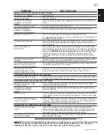
Appliance SHUTS OFF AND THE #3 LIGHT FLASHES
The hopper is out of pellets
-
Refi ll the hopper.
The hopper lid is open.
-
Close the hopper lid
The burnpot is not seated
completely into the burner
housing.
-
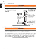
Insure the burnpot locating notch engages with the ignitor and that the burnpot
sits fl at.
The burnpot holes are blocked
-
Remove the burnpot and thoroughly clean it.
The air inlet,the interior
chambers, or the exhaust
system has a partial blockage.
-
Follow all cleaning procedures in the maintenance section of the manual.
The auger shaft is jammed.
-
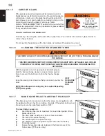
Start by disconnecting the power supply and emptying the hopper.
-
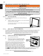
The auger shaft may be jammed. For more information see “IN THE EVENT OF
A JAMMED AUGER” section.
The auger motor has failed.
-
Remove the auger motor from the auger shaft and try to run the unit. If the
motor will turn, the shaft is jammed on something. If the motor will not turn, the
motor is defective.
The low limit switch has
malfunctioned.
-
Temporarily bypass the low limit switch by disconnecting the two brown wires
and connecting them together with a short piece of wire, then plug the appliance
back in. If the appliance comes back on and works, you need to replace the low
limit switch.
CAUTION: This is for testing only!
Leaving the switch bypassed
will cause the blowers to remain on constantly and the auger will continue
to feed even if the fi re is out. Do not operate the unit with the low limit switch
bypassed.
The fuse on the control board
has blown.
-
Remove the control board. If the fuse appears to be defective, replace it with a 5
amp 125 volt fuse. Plug the appliance back in and try to run the unit.
The control board is not sending
power to the low limit switch or
other auger system components.
-
There should be an approximate 5 volt current going to the low limit switch after
the appliance has been on for 10 minutes.
Flame has gone out in burn
pot while at feed rate 1. A few
unburned pellets are in the pot.
-
Feed rate is too low for the quality and moisture content of pellet fuel that is
being used. Adjust trim of combustion blower down or auger motor up.
APPLIANCE SHUTS OFF AND #4 .LIGHT FLASHES.
The high limit switch has tripped.
-
This is a manual reset switch but should only be done by a qualifi ed technician
once the cause of failure has been determined.
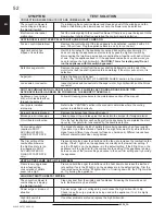
APPLIANCE FEEDS PELLETS BUT WILL NOT IGNITE
Blockage in igniter tube or inlet
for the ignitor tube.
-
Ensure that the air intake hole is clear, it is located on the side of the igniter
housing on the back of the fi rewall.
The burnpot is not seated
completely into the burner
housing.
-
Place the burnpot so that the locating notch engages with the ignitor and the
burnpot is sitting fl at
Defective ignitor.
-
Put power directly to the ignitor and observe the tip of the ignitor from the front
of the appliance. Within two minutes the tip should glow, if it does not, the ignitor
is defective.
The control board is not sending
power to the ignitor.
-
Check the voltage going to the ignitor during start up. It should be at full current
(115 volts). If the voltage is lower than full current, check for problems with the
wiring. If no problems are found, the board is defective.
SMOKE SMELL IS COMING BACK INTO THE HOME
There is a leak in the vent pipe
system
-
Inspect all the vent pipe connections. Make sure they are sealed with RTV
silicone that has a temperature rating of 260°C (500°F) or higher. Seal joints
with UL-181-AP foil tape and insure the square to round adapter piece on the
combustion blower has been properly sealed with the same RTV.
The gasket on the combustion
blower has deteriorated.
-
Inspect both gaskets on the combustion blower to make sure they are in good
shape. Replace if necessary.
NOTE: When the green light fl ashes it is indicating it is in pilot mode, or low burn. The Heat level setting
light will not change, and will still display the current manual setting of heat level. The only way to
indicate that they are in pilot or low burn is when the power light is fl ashing green.
Summary of Contents for NPI45
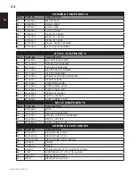
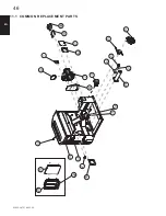
Page 48: ...W415 1472 04 21 15 48 EN 67 20 29 58 41 38 43 44 63 57 60 6 11 3 NPI45 REPLACEMENT PARTS...
Page 54: ...W415 1472 04 21 15 54 EN 14 0 SERVICE HISTORY 43 1...
Page 55: ...W415 1472 04 21 15 55 EN 15 0 NOTES 44 1...
Page 106: ...106 W415 1472 04 22 15 FR 67 20 29 58 41 38 43 44 63 57 60 6 11 3 PI CES DE RECHANGE DU NPI45...
Page 114: ...114 W415 1472 04 22 15 FR 15 0 NOTES 44 1...
Page 115: ...115 W415 1472 04 22 15 FR 44 1...


