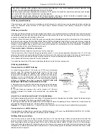
Shut down
1.
Turn the control knob to “0" setting.
2.
Lift the safety lever.
3.
Turn off the oil tank fuel supply valve.
The oil tank fuel supply valve should always be shut off when the oil stove is not in operation.
ADJUSTMENTS
Oil flow adjustments
The oil flow setting is done by the manufacturer and
normally should not require any adjustments. These
adjustments if required must be done by a qualified
technician.
Always burn the stove on low for at least 15 minutes before
attempting to adjust the flow.
Turn the screw only a quarter turn at a time. Walt 10 to
15 minutes between adjustments to allow the fire to
stabilise.
If the burner fails to respond to the control knob settings,
other possible causes should be checked (chimney draft,
dirty filter or the oil supply line) prior to attempting to adjust
the carburetor.
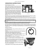
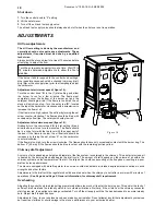
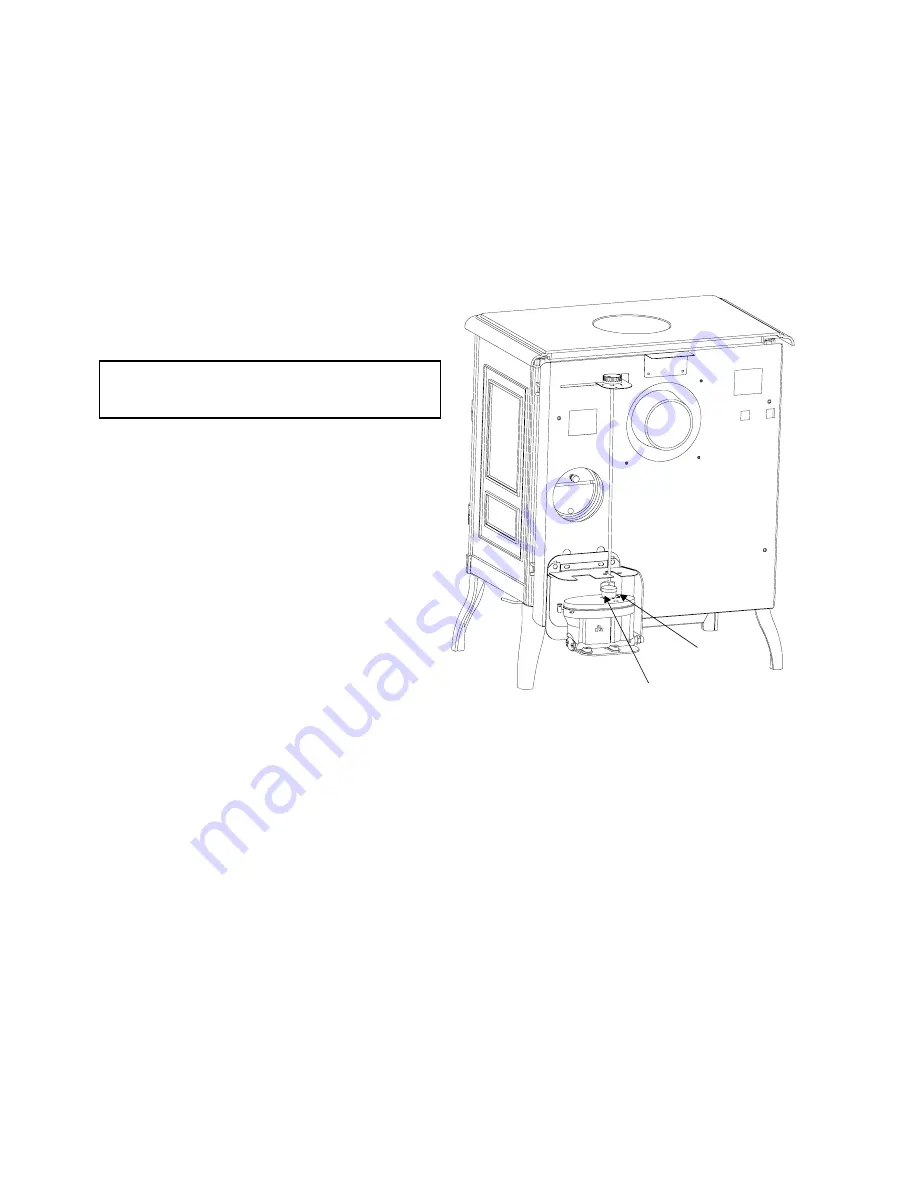
Adjustment at minimum speed ( figure 16) :
Turn the control knob
‘A’
to the (1) dial setting and allow
the burner to run for a few minutes. The flame must
completely cover the bottom of the burner pot and the
catalyser should glow red. If the flame is too small, the oil
stove will quickly soot up. Turn the set screw
‘B’
, located
on the top of the carburetor, clockwise with a screwdriver to
increase the flow of oil.
If the flame is too high, reduce the oil flow by turning the set
screw counter-clockwise. The flames should be blue with
occasional yellow tips. The catalyser should glow red.
Adjustment at maximum speed (figure 16) :
Gradually turn the control knob
‘A’
to dial setting (6) and
allow the burner to run for a few minutes. The flame should
be in a cone form with the top level with the upper part of
the door. If the flame is too low, the oil flow rate should be
increased by turning the set screw ‘
C
’ on the carburetor
counter-clockwise.
If the flame is too high, turn the screw clockwise. The flames should have only occasional contact with the burner ring. The
bottom 2" (50 mm) of the flames should be blue in colour with the remaining portion yellow.
Chimney draft adjustment
A volume of air, depending on height and diameter of the flue system, is contained in the chimney. This air starts to rise as it
is heated by the burning stove and begins the draft cycle. The amount of draft depends on the volume of air within the
chimney system and the temperature of that air. Too large a flue could cause cooling of the flue gases, resulting in a poor
draft and stove performance.
The stove is equipped with a draft regulator to ensure a constant and stable air intake despite external variations in wind
strengths and other factors.
Adjustments to the draft with the regulator should be carried out when the chimney is hot (after a minimum 30 minutes of
operations).
See Page 4 and Page 5, General information, for chimney draft requirement.
Overheating
Adjusting the control knob to a high setting prematurely allows too much oil to enter the burning pot. This and/ or the lack of
sufficient draft creates a fire intensity which in turn creates vibrations. Similarly, if the oil stove or the chimney connector
start to glow red, the appliance is being overheated. Turn off the oil supply until the fire has decreased to a normal steady
burn. Adjust draft to specifications.
Adjustments, if any, to your oil stove have been made by your installer. Do not attempt any further adjustments yourselves
but report any failures or shortcomings in the stove’s performance to your authorized dealer.
Document n° 1092-1 EN ~ 04/02/2002
10
Figure 16
A
B
C


