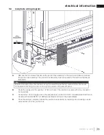
W415-1673 / A / 10.07.19
EN
18
installation
3.2
mounting plate installation (for concrete)
A.
Level and affi x the mounting ‘template’ to the wall at the desired location and height.
B.
Using the ‘template’, mark the holes for the vent, gas and electrical inlets, and wall anchor locations. See
“MINIMUM CLEARANCES TO COMBUSTIBLES” section.
NOTE : Use the appropriate cutout on the mounting ‘template’ for non-combustible material.
C.
Remove the mounting ‘template’ from the wall and cut/drill the required holes as marked.
D.
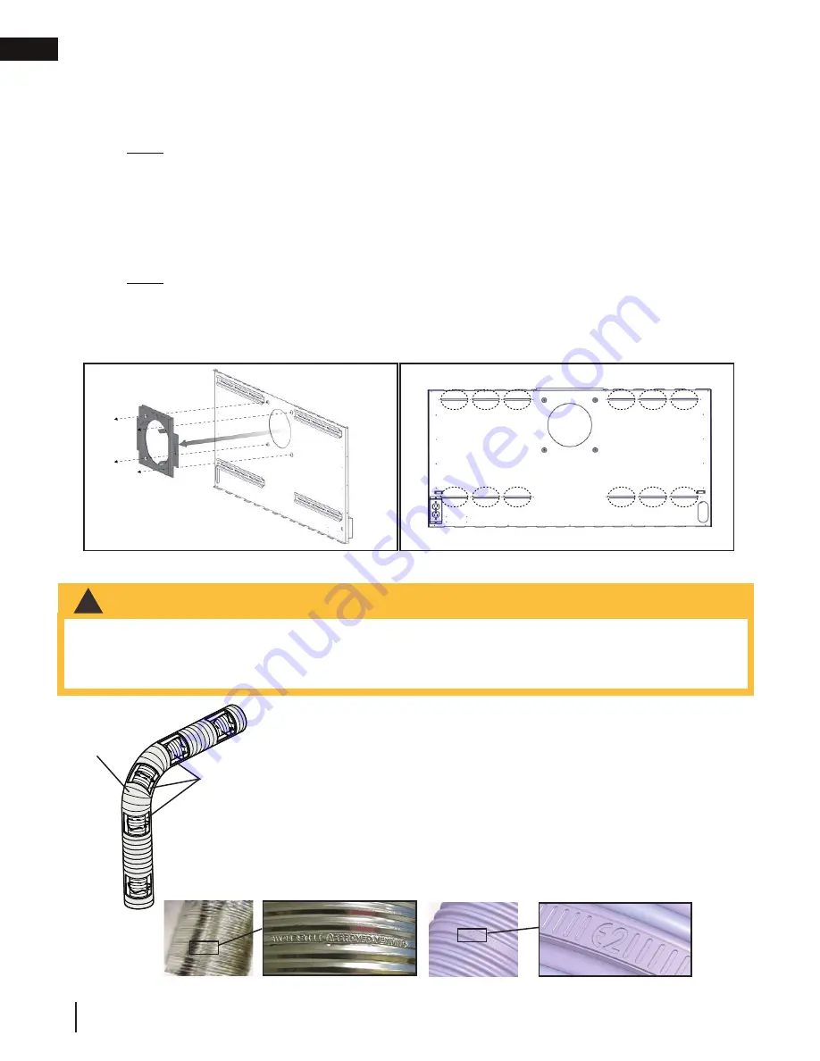
Remove the four fasteners that secure the fi restop spacer assembly (complete with the wall plate) from
the wall mounting plate.
(FIG. 1)
E.
Place the wall mounting plate against the non-combustible wall and align the wall mounting plate hole
with the vent hole. Level the wall mounting plate. Once leveled, secure the wall mounting plate to the wall
through the dimpled holes using four fasteners (not supplied).
NOTE : For non-combustible installation, wall anchors (not supplied) will be required
.
F.
Look through slotted holes on the wall mounting plate for pre-marked mounting locations and secure wall
mounting plate using a minimum of one fastener per corner (not supplied).
(FIG. 2)
G.
See the following sections up to the “FINISHING” section for venting and mounting instructions.
FIG.2
3.3 using
fl exible vent components
FIG.1
For safe and proper operation of the appliance, follow the venting instructions
exactly.
The vent system must be supported approximately every 3 feet (0.9m) for
both vertical and horizontal runs. Use Wolf Steel Ltd. support ring assembly
or equivalent noncombustible strapping to maintain the minimum clearance to
combustibles for both vertical and horizontal runs.
All inner fl ex pipe and outer fl ex pipe joints may be sealed using high temperature
red RTV silicone W573-0002 (not supplied) or the high temperature sealant W573-
0007 Mill Pac (not supplied). However, the high temperature sealant W573-0007
Mill Pac (not supplied) must be used on the joint connecting the inner fl ex pipe and
the exhaust fl ue collar.
Use only approved fl exible vent pipe kits marked:
“Wolf Steel Approved Venting” or “E2” as identifi ed by the stamp only on the fl ex pipes.
Elbow
Spacers
•
Do not allow the inner fl ex pipe to bunch up on horizontal or vertical runs and elbows. Keep it pulled tight.
•
Spacers are attached to the inner fl ex pipe at predetermined intervals to maintain an even air gap to the outer
fl ex pipe. This gap is required for safe operation. A spacer is required at the start, middle, and end of each
elbow to ensure this gap is maintained. These spacers must not be removed.
!
WARNING


