background image

6

W415-0847 / A / 06.08.10

4.6

This gas appliance should be installed and serviced by a quali

fi

 ed installer  to conform with local codes.  

Installation practices vary from region to region and  it is important to know the speci

fi

 cs that apply to your 

area, for example: in Massachusetts State:
• 

The appliance off valve must be a “T” handle gas cock.

• The 

fl

 exible connector must not be longer than 36“.

• 

The appliance is not approved for installation in a bedroom or bathroom unless the appliance is a direct 
vent sealed combustion product.

• 

A carbon monoxide detector is required in all rooms containing gas 

fi

 red appliances.

• WARNING: 

This product must be installed by a licensed plumber or gas 

fi

 tter when installed within the 

commonwealth of Massachusetts.

• 

Un-vented room appliance shall be installed in accordance with 527 CMR 30.00 and 248 CMR 3.00 
through 7.00.

• 

Sellers of un-vented propane or natural gas-

fi

 red space / room appliances shall provide to each purchaser 

a copy of 527 CMR 30.00 upon the sale of the appliance from http://www.napoleon

fi

 replaces.com/

Webshare/installation_manuals/mass_requirements.pdf

In absence of local codes, install the appliance to the current National Fuel Gas Code, ANSI Z223.1 
Installation Code which can be obtained from:

     American National Standards Institute Inc.          or 

     National Fire Protection Association Inc.

  1430 

Broadway 


Batterymarch 

Park


         New York, NY 10018 

                         Quincy, MA 02269

The appliance and its individual shutoff valve must be disconnected from the gas supply piping system during 
any pressure testing of that system at test pressures in excess of 1/2 psig (3.5 kPa). The appliance must be 
isolated from the gas supply piping system by closing its individual manual shutoff valve during any pressure 
testing of the gas supply piping  system at test pressures equal to or less than 1/2 psig (3.5 kPa). When 
installed with a blower the junction box must be electrically connected and grounded in accordance with local 
codes. In the absence of local codes, use the current ANSI / NFPA 70 National Electric Code. In the case 
where the blower is equipped with a power cord it must be connected into a properly grounded receptacle. 
The grounding prong must not be removed from the cord plug.

As long as the required clearance to combustibles is maintained, 
the most desirable and bene

fi

 cial location for the appliance is in the 

center of a building, thereby allowing the most ef

fi

 cient use of the 

heat created. The location of windows, doors and the traf

fi

 c 

fl

 ow in 

the room where the appliance is to be located should be considered. 

If the appliance is installed directly on carpeting, vinyl tile or other 
combustible material other than wood 

fl

 ooring, the appliance shall be installed on a metal or wood panel 

extending the full width and depth. 

NOTE: This does not apply to stoves.

We suggest that our gas 
hearth products be installed 
and serviced by professionals 
who are certified in the U.S. 
by the National Fireplace 
Institute

® (NFI) as NFI Gas 

Specialists

www.nficertified.org

Summary of Contents for Torch GVFT8N

Page 1: ... the vicinity of this or any other appliance WHAT TO DO IF YOU SMELL GAS Do not try to light any appliance Do not touch any electrical switch do not use any phone in your building Immediately call your gas supplier from a neighbour s phone Follow the gas supplier s instructions If you cannot reach your gas supplier call the fire department Installation and service must be performed by a qualified ...

Page 2: ...3 GAS INSTALLATION 10 3 4 GAS PRESSURE 11 4 0 FRAMING 12 4 1 CLEARANCE TO COMBUSTIBLES 12 5 0 FINISHING 13 5 1 MOUNTING CABINET INSTALLATION 13 5 2 DOOR REMOVAL 14 5 3 FRAME INSTALLATION 15 5 4 LOGO PLACEMENT 16 5 5 GLASS MEDIA INSTALLATION 16 5 6 LK8 LIGHT INSTALLATION OPTIONAL 17 6 0 ELECTRICAL INFORMATION 18 7 0 OPERATION 19 8 0 ADJUSTMENTS 20 8 1 VENTURI ADJUSTMENT 20 8 2 FLAME CHARACTERISTICS...

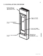
Page 3: ...RVIEW Mounting cabinet see MOUNTING CABINET INSTALLATION section Frame see FRAME INSTALLATION section Door see DOOR REMOVAL section Glass see GLASS REMOVAL section Logo see LOGO PLACEMENT section Rating Plate see RATING PLATE INFORMATION section ...

Page 4: ...nce Check with your local hearth specialty dealer for safety screens and hearth guards to protect children from hot surfaces These screens and guards must be fastened to the floor Any safety screen or guard removed for servicing must be replaced prior to operating the appliance It is imperative that the control compartments burners and circulating blower and its passageway in the appliance are kep...

Page 5: ...THE INFLUENCE OF ALCOHOL THOSE AT HIGH ALTITUDES ARE MORE AFFECTED BY CARBON MONOXIDE THAN OTHERS THE HEATER IS ONLY FOR USE WITH THE TYPE OF GAS INDICATED ON THE RATING PLATE THIS HEATER IS NOT CONVERTIBLE FOR USE WITH OTHER GASES OBJECTS PLACED IN FRONT OF THE HEATER SHOULD BE KEPT A MINIMUM OF 48 AWAY FROM THE GLASS FRONT FACES OF THE HEATER USE ONLY WOLF STEEL APPROVED OPTIONAL ACCESSORIES AND...

Page 6: ...2269 The appliance and its individual shutoff valve must be disconnected from the gas supply piping system during any pressure testing of that system at test pressures in excess of 1 2 psig 3 5 kPa The appliance must be isolated from the gas supply piping system by closing its individual manual shutoff valve during any pressure testing of the gas supply piping system at test pressures equal to or ...

Page 7: ...CATED ON THE RATING PLATE THIS APPLIANCE IS NOT FIELD CONVERTIBLE FOR USE WITH OTHER GASES THIS IS A GAS FIRED UNVENTED ROOM HEATER THAT REQUIRES ADEQUATE COMBUSTION AND VENTILATION AIR ALTITUDE INPUT ORIFICE MANIFOLD PRESSURE 3 5 WATER COLUMN MINIMUM SUPPLY PRESSURE 4 5 WATER COLUMN MAXIMUM SUPPLY PRESSURE 7 0 WATER COLUMN MANIFOLD PRESSURE 10 WATER COLUMN MINIMUM SUPPLY PRESSURE 11 WATER COLUMN ...

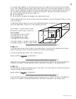
Page 8: ...es or openings such as kitchen pass throughs etc the volume of those rooms may be added to the total Multiply the room volume by 1000 and divide this amount by 50 to determine the maximum BTU hr that the space can support with adequate combustion and ventilation air Add the Btu hr of all fuel burning appliances located within the space such as gas furnace gas water appliance etc Do not include dir...

Page 9: ... BTU hr of gas input During the cold weather season indoor humidity levels tend to be low Consequently this water vapour can enhance the living space However if a problem should occur A Ensure sufficient combustion and circulation air B Use a dehumidifier C Do not use the unvented room appliance as a primary heat source Without sufficient fresh air for proper operation poor fuel combustion can res...

Page 10: ...RE EXPLOSION OR ASPHYXIATION ENSURE THERE ARE NO IGNITION SOURCES SUCH AS SPARKS OR OPEN FLAMES SUPPORT GAS CONTROL WHEN ATTACHING GAS SUPPLY PIPE TO PREVENT DAMAGING GAS LINE ALWAYS LIGHT THE PILOT WHETHER FOR THE FIRST TIME OR IF THE GAS SUPPLY HAS RUN OUT WITH THE GLASS DOOR OPENED OR REMOVED PURGING OF THE GAS SUPPLY LINE SHOULD BE PERFORMED BY A QUALIFIED SERVICE TECHNICIAN ASSURE THAT A CONT...

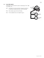
Page 11: ... 3 4 1 Outlet pressure can be checked by removing cap A using a 3 16 Allen key and replacing it with a 1 8 NPT barb fitting 3 4 2 Place pressure gauge tube over the fitting 3 4 3 Once completed be sure to replace the cap A A 1 8 NPT BARB FITTING 10 PROPANE GAS PRESSURE GAUGE NATURAL GAS 3 5 3 4 GAS PRESSURE ...

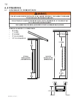
Page 12: ...ABINET IS DESIGNED TO BE INSTALLED ON FINISHED SURFACES THIS APPLIANCE CAN BE RECESSED INTO AN ALCOVE A MAXIMUM OF 12 PROVIDED THAT ALL CLEARANCES ARE MAINTAINED THE CABINET MAY BE INSTALLED DIRECTLY ONTO A COMBUSTIBLE SURFACE 4 1 CLEARANCE TO COMBUSTIBLES WARNING TYPICAL INSTALLATION OUTSIDE WALL ALCOVE INSTALLATION INSIDE WALL 18 MIN 8 MIN 8 12 MAX 18 MIN 8 MIN 12 MAX 1 MIN 1 MIN 4 0 FRAMING ...

Page 13: ...ate fasteners NOTE The Torch has been designed to have a 1 2 clearance between the rear outer panel and the mounting surface 5 1 4 Start the fasteners into each of the six remaining mounting holes Align the keyholes of the frame to the heads of the fasteners and slide the frame down onto the fasteners Ensure the frame is plumb and level before tightening the fasteners NOTE It is recommended that t...

Page 14: ... pins along the top edge replacing them is optional To secure the door in place use the supplied hitch pins as illustrated WARNING GLASS MAY BE HOT DO NOT TOUCH GLASS UNTIL COOLED THE DOOR LATCHES ARE PART OF A SAFETY SYSTEM AND MUST BE PROPERLY ENGAGED DO NOT OPERATE THE APPLIANCE WITH LATCHES DISENGAGED FACING AND OR FINISHING MATERIALS MUST NOT INTERFERE WITH AIR FLOW THROUGH AIR OPENINGS LOUVR...

Page 15: ... screws 5 3 7 Once the frame is perfectly square and the control door will close without rubbing against the sides of the frame tighten all screws 5 3 8 Open the control door 5 3 9 Insert the door stop chain into the receiving slot in the control door 5 3 10 Insert the door stop chain into the receiving slot in the frame so that when fully open the control door has a clear ance of 1 8 to the finis...

Page 16: ...l residue that needs to be cleaned prior to installation Clean the glass with mild dish soap drain rinse thoroughly and dry before placing around the burner CLEANING CRYSTALS To help maintain the luster and beauty of these crystals over time carefully polish them by using a soft lint free cloth If they become heavily soiled you may use a mild detergent and wash them individually by hand as you wou...

Page 17: ...ame 5 6 5 Connect the light assemblies to the appropriate flags on the wire harness The wire harness is labeled TR top right BR bottom right TL Top left and BL bottom left 5 6 6 Secure the wires into the clips at both sides and the bottom of the frame Use the extra clips provided to retain any loose wires 5 6 7 Re attach frame onto appliance 5 6 8 Open the control panel door leave the wires connec...

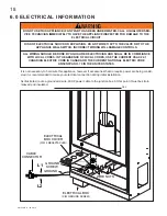
Page 18: ...CE WALL SWITCH INCORRECT WIRING WILL DAMAGE CONTROLS ALL WIRING SHOULD BE DONE BY A QUALIFIED ELECTRICIAN AND SHALL BE IN COMPLIANCE WITH LOCAL CODES IN THE ABSENCE OF LOCAL CODES USE THE CURRENT CSA C22 1 CANADIAN ELECTRIC CODE IN CANADA OR THE CURRENT NATIONAL ELECTRIC CODE ANSI NFPA NO 70 IN THE UNITED STATES It is not necessary to hard wire this appliance however if accessories that do require...

Page 19: ...control system and any gas control which has been under water WHAT TO DO IF YOU SMELL GAS Do not try to light any appliance Do not touch any electric switch do not use any phone in your building Immediately call your gas supplier from a neighbour s phone Follow the gas supplier s instructions If you cannot reach your gas supplier call the fire department LIGHTING INSTRUCTIONS 1 STOP Read the safet...

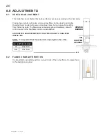
Page 20: ...me lifting from the burner ports The flame may not appear yellow immediately allow 15 to 30 minutes for the final flame color to be established AIR SHUTTER ADJUSTMENT MUST ONLY BE DONE BY A QUALIFIED INSTALLER NOTE It is important that the venturi sits down tight on the orifice 49 3 VENTURI BURNER AIR SHUTTER OPENING AIR SHUTTER OPENINGS LP 3 16 DIA NG 1 16 DIA 8 2 FLAME CHARACTERISTICS It is impo...

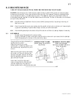
Page 21: ...consult your authorized dealer 9 0 3 Check that the gasketing on the sides and top of the door are not broken or missing Replace if necessary Visually inspect the appliance for carbon buildup Using a small whisk or brush brush off the excess carbon and vacuum up or sweep into the garbage Check the appliance for corrosion of the main burner base 9 1 CLEANING This procedure must be performed by a qu...

Page 22: ...sket W562 0008 and the glass W300 0110 Set new glass into the frame and gently bend tabs into the gasket to secure Ensure that the gasketed end of the glass is placed into the top of the door frame NOTE Care must be taken when removing and disposing of any broken glass or damaged components Be sure to vacuum up any broken glass from inside the appliance before operation GLASS RETAINERS GASKET GLAS...

Page 23: ...E TO USE ONLY PARTS SPECIFICALLY APPROVED WITH THIS APPLIANCE MAY RESULT IN PROPERTY DAMAGE OR PERSONAL INJURY WARNING COMPONENTS REF PART NO DESCRIPTION 1 W225 0251 DOOR FRAME 2 W562 0008 DOOR GASKET 3 W010 1959 GLASS C W GASKET 4 W300 0132 GLASS 5 W100 0104 BURNER 6 W200 0263 IGNITOR COVER 7 W200 0262 BURNER COVER 8 W725 0060 NATURAL GAS VALVE 3 5 W C 9 W137 0001 CERAMIC CATALYST 10 W662 0006 OX...

Page 24: ...24 W415 0847 A 06 08 10 ACCESSORIES REF PART NO DESCRIPTION 21 TMCSS MOUNTING CABINET 22 TFSSO FRAME KIT 23 LK8 LIGHT KIT 22 21 ...

Page 25: ...re and orifice size as specified by the rating plate values White grey film forms Sulphur from fuel is being deposited on glass logs rocks media or combustion chamber surfaces Clean the glass with a gas appliance glass cleaner DO NOT CLEAN GLASS WHEN HOT If deposits are not cleaned off regularly the glass may become permanently marked No gas to the main burner switch is on Switch is defective Conn...

Page 26: ... of NAPOLEON with respect to the NAPOLEON gas heater and any other warranties expressed or implied with respect to this product its components or accessories are excluded NAPOLEON neither assumes nor authorizes any third party to assume on its behalf any other liabilities with respect to the sale of this product NAPOLEON will not be responsible for over firing downdrafts spillage caused by environ...

Page 27: ...27 W415 0847 A 06 08 10 13 0 SERVICE HISTORY 43 1 ...

Page 28: ...28 W415 0847 A 06 08 10 44 1 14 0 NOTES ...

Reviews: