background image


3-4 

Operating Instruction


3.2.2 Short test mode 


Setting test time 
and open level


Wait five minutes between three short test cycles. 

 
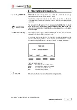
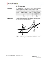
Using this test it is possible to do a short test with an high level of field, in 
fact the maximum current is 1250 A for a maximum time of 5 seconds.  
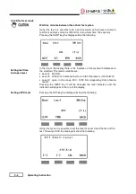
Pressing the SHRT key the display will be the following: 

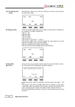
In the top of the display there is the indication of the level with reference to 
the standard. The levels available are : 

  Level 4  300 A/m 

  Level 5  1000 A/m if antenna factor is 

 0,87 otherwise is (1000/0.87)*K.


  Level X  open,  in  the  range  300  -  1000  A/m  (depending  from  antenna 

factor) 

Pressing  the  NEXT  key  it  will  be  changed  the  level  selected,  and  the 
indication will appear in the top of the display. 


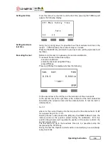
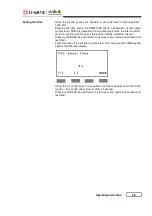
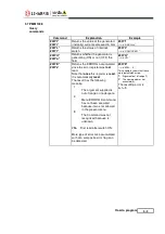
Setting LEVX level


Pressing the SET key the display will show the following: 

Using this menu it is possible to set the level of Level X and the time of the 
test. Pressing LEVX the display will show the following  

Summary of Contents for PMM 1008

Page 1: ...ou can find the Series Number on the rear panel of the instrument Series Number is in the form 0000X00000 The first four digits and the letter are the Series Number prefix the last five digits are the...

Page 2: ...vice Nevertheless even this product will eventually become obsolete When that time comes please remember that electronic equipment must be disposed of in accordance with local regulations This product...

Page 3: ...llation 2 10 Safety Interlock Page 2 1 2 1 2 1 2 1 2 2 2 2 2 2 2 3 2 3 2 8 3 Operation instructions 3 1 Starting PMM 1008 3 2 Main menu display 3 2 1 Continuous test mode 3 2 2 Short test mode 3 2 3 E...

Page 4: ...1008 with Circular loop 40cm Characteristics of the field generated by a square induction coil 3dB area of the field generated by a square induction coil 3dB area of the field generated by a square in...

Page 5: ...to it In case of connection of the device to the power mains make sure before connection that the voltage selected on the voltage switch and the fuses are adequate for the voltage of the actual mains...

Page 6: ...035 Cisano sul Neva SV ITALY based on the following harmonized European Standards successfully applied Safety EN 61010 1 undated reference applies to all editions EMC EN 61326 1 undated reference appl...

Page 7: ...onsidering the antenna factor the system includes the antenna formed by one coil and the antenna mast The correct output current is automatically set and regulated by the generator PMM 1008 is designe...

Page 8: ...rrent Output voltage Without load Output current Max continuos Max short Modes Continuous Short Manual Ramp Internal timer Continuous mode Short mode Timer resolution Continuous mode Short mode Size G...

Page 9: ...General Information 1 3 Fig 1 1 PMM 1008...

Page 10: ...1 4 General Information 1 7 Front panel Fig 1 2 Front Panel Legend 1 LCD display 2 Functional keys 3 Operate led 4 Stand by led 1 2 3 4...

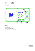
Page 11: ...General Information 1 5 1 8 Rear panel Fig 1 3 Rear Panel Legend 1 Mains plug IEC CEE22 2 power switch 3 RS232 485 interface DB9 4 User I O port DB15 5 current output connector 14 mm bolt 5 3 1 2 4...

Page 12: ...1 6 General Information This page has been left blank intentionally...

Page 13: ...referring to the accessories check list enclosed with the Users Manual Notify any damage to the carrier personnel as well as the NARDA Representative This is a Safety Class I equipment it is provided...

Page 14: ...d to NARDA for service please complete the service questionnaire enclosed with the Users Manual and attach it to the instrument To minimize the repair time be as specific as possible when describing t...

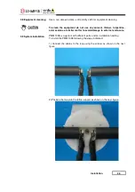
Page 15: ...ne acid acetone or similar matter to avoid damage to external enclosure 2 9 System Installation PMM 1008 is a system with different parts and an installation needing To install the PMM 1008 following...

Page 16: ...2 4 Installation 3 Lock the loop to the support using the six screws...

Page 17: ...Installation 2 5 4 Lock the antenna mast on the Cart using the screw on the bottom...

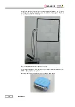
Page 18: ...ition desired using the screw mounted on the support The final mounting should be the following 6 Put the generator on his support on the Cart 7 Connect the cables from the loop to the output current...

Page 19: ...antenna produces magnetic field the field is high in the center of the loop set the generator positioning outside of the loop like in the previous figure Fig 2 1 PMM 1008 with Square loop 1m Fig 2 2 P...

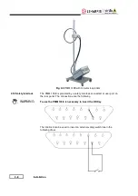
Page 20: ...ock WARNING The PMM 1008 is provided by a safety interlock connected at user port on the rear panel The connections are the following To use the PMM 1008 is necessary to insert the HD Key The interloc...

Page 21: ...the PMM 1008 For connect the instrument at distribution network don t use extension lead or adapter Connect the power supply cable and HD Key to the rear panel connector and switch on the standby led...

Page 22: ...ear in the top of the display Select your field and press ON to start the test Pressing the SET key the display will show the following Setting LEVX open level Using this menu it is possible to set th...

Page 23: ...l show the following In the second row at the left there is the indication of time in seconds In the second row at the right there is the indication of the field calculated considering the output curr...

Page 24: ...is the indication of the level with reference to the standard The levels available are Level 4 300 A m Level 5 1000 A m if antenna factor is 0 87 otherwise is 1000 0 87 K Level X open in the range 300...

Page 25: ...tor variac to set the correct current this position will be stored for the test Pressing the BACK key will return in previous menu setting open level and test time From this menu it is possible to set...

Page 26: ...there is the indication of the decreasing time in seconds Starting the test after pressed the ON key the PMM 1008 will move the internal variac at the position stored during the calibration After thi...

Page 27: ...tion in the right side the indication of the field Pressing the and keys it is possible to increase or decrease the field level If the band selected is 100 A the maximum current is 160 A and the maxim...

Page 28: ...stored position and then will regulate around it The calibration can be done for the continuous test CONT or for the short test SHRT or both Pressing CONT key the PMM 1008 will calibrate all the cont...

Page 29: ...CT key from the setup menu the display will be the following Pressing and keys the PMM 1008 will change the antenna factor When it is changed an antenna factor it is necessary to do a calibration beca...

Page 30: ...Instruction 3 2 7 Error message If the antenna is disconnected after some seconds the PMM 1008 will display the error message LOOP OPEN In this case check all the connections between the generator an...

Page 31: ...2 Short duration LEVEL MAGNETIC FIELD LEVEL MAGNETIC FIELD 1 1 1 Not applicable 2 3 2 Not applicable 3 10 3 Not applicable 4 30 4 300 5 100 5 1000 4 2 Induction coil The PMM 1008 is supplied with a 1...

Page 32: ...d by a square induction coil 1m side in its plane Fig 4 3 3dB area of the field generated by a square induction coil 1m side in the mean orthogonal plane component orthogonal to the plane of the coil...

Page 33: ...y Communication is done at 9600 Baud with 8 bit 1 stop bit and no parity The communication uses strings with variable byte width The characters used inside the strings are in ASCII format 00 127 at 7...

Page 34: ...ield level Note that this command is not recognized if received within sub menus 00C2 3 A m will be generated 00Sn where n is the level in the range 4 5 which refer to the related field X is the open...

Page 35: ...ter was last read Note that once this register is read it is automatically reset The result has the following meaning 1 The argument supplied is out of range or inadequate 4 Menu ERROR A command has n...

Page 36: ...5 4 How to program This page has been left blank intentionally...

Page 37: ...ents For the software to operate properly the user s Personal Computer should be equipped with the following 486 Processor or Pentium 16 Mb of RAM at least 10 Mb of free space on hard disk 1 free seri...

Page 38: ...he PMM 1008 5 When the upgrade procedure is completed correctly the software will display the following message PMM 1008 is now updated with the new version of the internal firmware It is now possible...

Page 39: ...like to submit to the attention of our service organization is kept in great consideration Moreover we are continuously improving our quality but we know this is a never ending process We would be gl...

Page 40: ...Suggerimenti Commenti Note Suggestions Comments Note...

Reviews: